
User's Guide
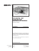

P25 Digital VHF Transmitter Instruction Manual
IM21-001
General Information
2
VT-4D150 Transmitter Family Models
There are four distinct models in the VT-4D150 Transmitter family each with different bands of
operation and power outputs. The four models are as follows:
• VT-4D140-2 136-150 MHz band, 0.5-2.0 Watt
• VT-4D140-8 136-150 MHz band, 2.0-8.0 Watt
• VT-4D160-2 150-174 MHz band, 0.5-2.0 Watt
• VT-4D160-8 150-174 MHz band, 2.0-8.0 Watt
The transmitters’ band of operation is determined by select components in the amplifi er.
Performance Specifi cations
Blank line
General
The following is a general set of specifi cations for the generic VT-4D150 transmitter. Additional
specifi cations, specifi c to individual modules may be found in their respective sub manuals.
Type: MT-4D Series Transmitter.
Family: VT-4D150 136 - 174 MHz.
Compatibility: MT-2, MT-3 and MT-4 Series Radio Systems, P25 interoperable.
Frequency Range: 136 to 150 MHz., 150 to 174 MHz
RF Power Output: 0.5 to 2.0 or 2.0 to 8.0 W Continuous.
Modulation: Analog: 11K0F3E or 16K0F3E (Frequency Modulation).
Project 25: 8K10F1E
System Impedance: 50 Ω; Type N connector.
Duty Cycle: 100%; Continuous operation from -30°C to +60°C.
Emissions: -70 dBc
Transmitter Mismatch Protection: 20:1 VSWR at all phase angles.
Operating Temperature Range: -30˚C to +60˚C.
Operating Humidity: 95% RH (non-condensing) at +25°C.
Operating Voltage: +13.8 Vdc Nominal (range +10 to +17 Vdc),
+9.5 Vdc Regulated.
Transmit Current: 1.7 Amps at 2 Watts RF Power Output,
2.8 Amps at 8 Watts RF Power Output
Front Panel Controls: NORM (repeat mode), OFF, and KEY TX (Tx on).
MIC MODE: ANALOG and DIGITAL.