DANIELS ELECTRONICS LTD. ® MT-3 RADIO SYSTEMS VHF TRANSMITTER INSTRUCTION MANUAL VT-3 29 - 50 MHz Covers model: VT-3H035-SWA3, VT-3H045-SWA3 Copyright © 1997 Daniels Electronics Ltd. All rights reserved. No part of this publication may be reproduced, stored in a retrieval system or transmitted in any form or by any means, electronic, mechanical, photocopying, recording or otherwise, without the prior written consent of Daniels Electronics Ltd. Issue: Issue Date: Printing Date: Part No.
1 GENERAL 1.1 Introduction The VT-3H040 transmitter is a low power, synthesized FM transmitter capable of operating in 20 kHz or 25 kHz channels and within one of two bands: 29 MHz to 38 MHz or 38 MHz to 50 MHz. The transmitter is rated for continuous duty at an RF output power of 3.0 Watt. The RF output power level is preset at the factory.
VT-3H040 VHF Amplifier: The amplifier module provides the final stages of RF power amplification and harmonic filtering for the transmitter. This manual is intended primarily as a reference since the amplifier module is adjusted at the factory. OS-3H040 Synthesizer: This manual pertains to the synthesizer module. Channel selection is described in the 'Transmitter Main Board' Manual.
1.4 Performance Specifications 1.4.1 General The following is a general set of specifications for the generic VT-3H040 transmitter. Additional specifications, specific to individual modules may be found in their respective submanuals. Type: MT-3 Series Transmitter Family: VT-3H040 Compatibility: MT-2 Series and MT-3 Series Radio Systems Frequency Range: 29.0 MHz to 50.0 MHz RF Power Output: 3.0 Watt Fixed (± 1.5 dB with temperature and supply voltage).
Standby Current and rise time: (See also 'Transmitter Main Board Instruction Manual) 95 % RF power, 95 % system deviation within; • 10 ms: typ. 185 mA (Mode 4); • 25 ms: typ. 160 mA (Mode 2); • 50 ms: typ. 15 mA (Mode 1); • Mode 3 not used in Synthesized Transmitters. DOC Type Approval RSS119 TBA, RSS122 TBA FCC Type Acceptance: H4J-VT-3H040-S Operating Temperature Range: -30˚ C to +60˚ C, optional -40˚ C temperature test. Operating Humidity: 95% RH (non-condensing) at +25˚ C.
1.4.2 Audio Specifications Audio Input: Balanced 600 ohm or unbalanced (optional). Input level sensitivity, -25 dBm to 0 dBm. Audio Response: Pre-emphasis (6 dB per octave); +1.0 to -2.0 dB from 300 Hz to 3 kHz; Flat Audio Response: +1 to -1 dB from 100 Hz to 3 kHz. Audio Deviation: Preset to ±3.0 kHz with a 1 kHz tone. Subtone Audio Input 1: 0.5 Vpp at 200 Hz for ±500 Hz deviation (internally adjustable). Subtone Audio Input 1 Frequency range: 60 Hz to 300 Hz. Subtone Audio Input 2: 0.
1.4.3 Physical Specifications Physical Dimensions: Width: Height: Depth: 7.1 cm (2.8 in) 12.8 cm (5.05 in) 19 cm (7.5 in) Module Weight: 1.5 kg (3.3 lbs) Corrosion Prevention: Anodized aluminum construction. Stainless steel hardware. Selectively conformal coated glass epoxy 2 and 4 layer printed circuitboards. Gold plated module connectors. Module Design: Compact Eurostandard modular design. Plug-in modules mate with Daniels standard M3 repeater subrack.
2 SYSTEM OVERVIEW 2.1 Transmitter Operation Several modules are integrated by the VT-3H040 Transmitter Main board to provide the complete transmitter. The Transmitter Main Board, Front Panel Board and Audio Processor are generic in that they apply to both transmitter models. The Front Panel Board and Audio Processor are soldered directly to the Transmitter Main Board and are treated collectively in the Transmitter Main Board Manual.
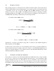
2.2 Frequency Selection The operating frequency is determined by the synthesizer channel number selected. The relation between channel number and operating frequency is, in general, specific to the family and model of transmitter. In the case of both the VT-3H035 and VT-3H045 transmitter models, each channel corresponds to either a 5 kHz or 6.25 kHz increment in frequency, depending on whether the channel number is below 5000 or above 4999 respectively; beginning at a base frequency of 29.0 MHz.
transmitter. Moreover, the surface of the Amplifier module that contacts the shell should be clean and free of foreign material. The enclosure is completed by the installation of front and rear plates which are fastened to the Transmitter Main Board (see Transmitter Main Board Manual for parts lists). Transmitter alignment is performed on a module by module basis and detailed steps are provided in the respective manuals.
FOR MODEL VT-3H035: Size of Frequency Change Modules to be Aligned less than ± 0.2 MHz Transmitter Main Board (Channel Change) between ± 0.2 and ± 0.5 MHz Transmitter Main Board (Channel Change), Audio Processor (see section 2.3.4) between ± 0.5 and ± 1.0 MHz Transmitter Main Board (Channel Change), Audio Processor (see section 2.3.4), Synthesizer check RF alarm thresholds (section 2.3.5) (?) ± 1.
unless it is confirmed that the original and replacement synthesizer have identical output power (within ± 0.5 dBm). 2.3.4 Deviation Setting The transmitter maximum deviation range is set by jumpers at the factory to ± 5.0 kHz for the VT-3H040 transmitter. However, under some conditions such as a large change in transmitter operating frequency, the deviation control may need adjustment.
2.5 Repair Note The transmitter is mainly made up of surface mount devices which should not be removed or replaced using an ordinary soldering iron. Removal and replacement of surface mount components should be performed only with specifically designed surface mount rework and repair stations complete with ElectroStatic Dissipative (ESD) protection. When removing Surface Mount Solder Jumpers, it is recommended to use solder braid in place of manual vacuum type desoldering tools when removing jumpers.