
Instruction Manual

DE
DANIELS
ELECTRONICS
2-8 MT-3 AM Transmitter Main Board Instruction Manual
2.3.4 PTT Time-Out-Timer
The PTT time-out-timer (TOT) is a relatively independent circuitry located on the Transmitter
Board. The TOT is powered from the continuous +9.5 Vdc supply (J34) and is programmable for
various time-out periods. The TOT input is normally high and in this state the timer is disabled.
When the input trigger level falls below +2.0 Vdc, the timer is activated, and the transmitter is
keyed. If the input trigger rises above +2.4 Vdc or if the time-out period is exceeded, the output
trigger will go high, disabling the transmitter. If the time-out period is exceeded, the TOT input
trigger must go high and then low again in order to rekey the transmitter.
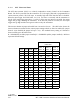
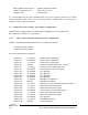
The time-out duration is jumper selectable from 1 second to 8 hours. The table below shows the
time-out duration in minutes for the various jumper settings which are listed as enabled (E: jumper
shorted - in) or disabled (D: jumper left open - out). The standard factory setting of 5 minutes is
shown in bold type in the table below.
D = DISABLED (no solder jumper installed), E = ENABLED (solder jumper installed). Bold text
represents default settings.
TIME-OUT DURATION
(MINUTES)
JU26= E JU26= D JU26= E
JU32 JU31 JU29 JU28 JU27= D JU27= E JU27= E
E E E E 0.01 0.01 0.01
E E E D 0.02 0.03 0.01
E E D E 0.04 0.06 0.02
E E D D 0.08 0.12 0.05
E D E E 0.15 0.23 0.10
E D E D 0.31 0.47 0.19
E D D E 0.62 0.94 0.38
E D D D 1.25 1.88 0.75
D E E E 2.5 3.75 1.5
DEED 5.0 7.5 3.0
DEDE 10 15 6.0
D E D D 20 30 12
DDEE406024
D D E D 80 120 48
D D D E 160 240 96
D D D D 320 480 192