User Manual


Table Of Contents
- 1GENERAL
- 1.1Introduction
- 1.2Performance Specification
- 2THEORY OF OPERATION
- 2.1Amplifier Operation
- 2.2Power Requirements
- 2.3RF Circuitry
- 2.3.1UT-3/400 Lowpass Filter
- 2.4Power Control Circuitry
- 2.5Power Sensing Circuitry
- 2.5.1Output Power Sense
- 2.5.2VSWR Sense
- 2.5.3VSWR Overload
- 3UT-3/400 AMPLIFIER ALIGNMENT
- 3.1General
- 3.2Repair Note
- 3.3Recommended Test Equipment List
- 3.4Printed Circuitboard Numbering Convention
- 3.5Standard Factory Settings and Jumper Configuration
- 3.6UT-3/400 AmplifierAlignment
- 3.6.1General
- 3.6.2UT-3/400 Amplifier Adjustment
- 3.6.2.1General Set-Up
- 3.6.2.2Output Power Alarm (Forward Power)
- 3.6.2.3Output Power
- 3.6.2.4Antenna VSWR Alarm (Reverse Power)
- 3.6.2.5Antenna VSWR Overload
- 3.6.2.6Procedure Verification
- 4ILLUSTRATIONS AND SCHEMATIC DIAGRAMS
- 4.1UT-3/400 UHF Amplifier Component Layout
- 4.2UT-3/400 UHF Amplifier Schematic Diagram
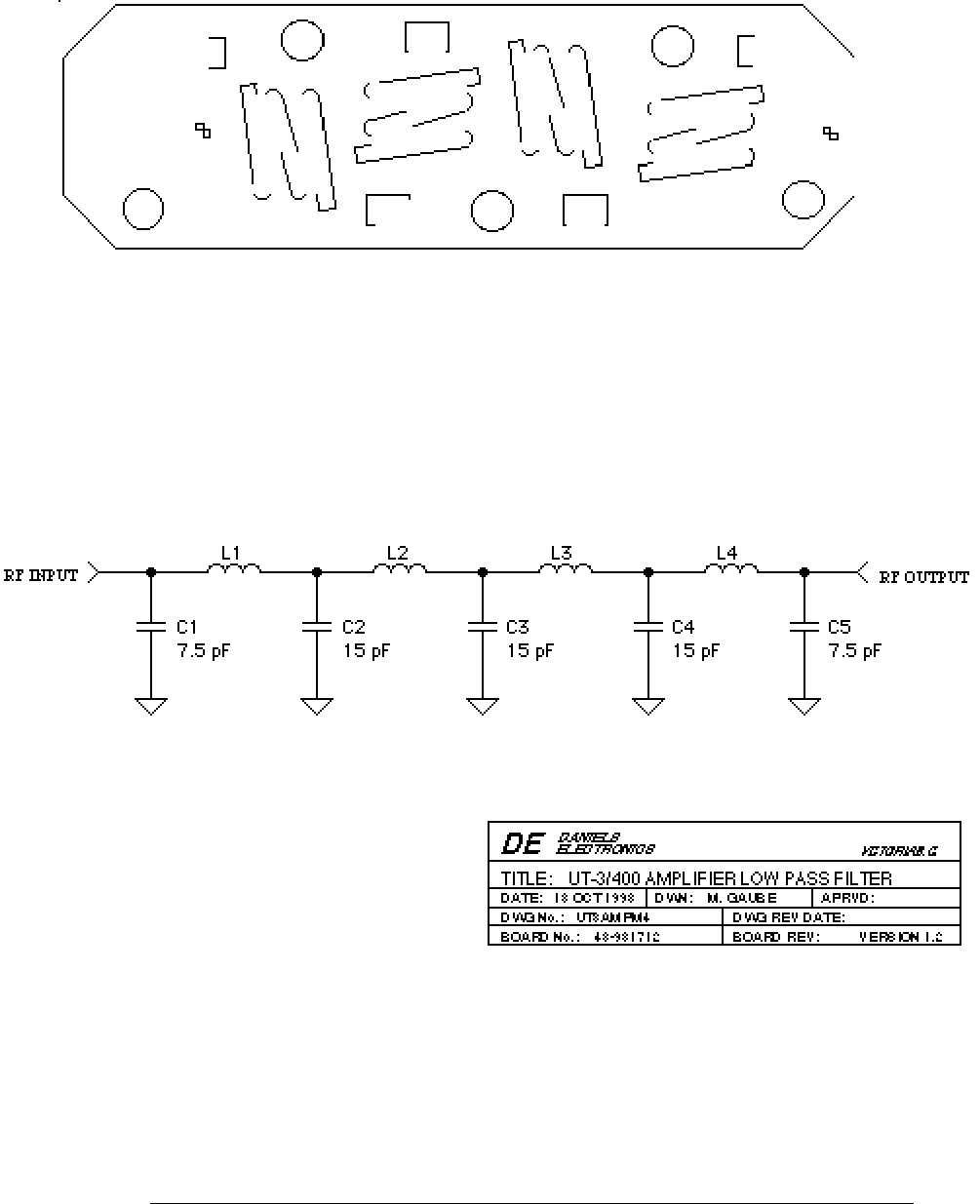
- 4.3UT-3/400 UHF Lowpass Filter Component Layout
- 4.4UT-3/400 UHF Lowpass Filter Schematic Diagram
- 5PARTS LISTS
- 5.1UT-3 / UT4 UHF Amplifier Electrical Parts List
- 5.2UT-3/400 UHF Amplifier Mechanical Parts List
- 5.3UT-3/400 UHF Low Pass Filter Electrical Parts List
- 6REVISION HISTORY