
User's Guide
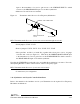
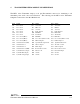


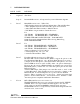

Table Of Contents

DE
DANIELS
ELECTRONICS
3-12 Transmitter Main Board Instruction Manual
MT-3 Transmitter (board version 43-920910 through 43-920911)
• J6 installed (synthesizer always powered up by +9.5V SWITCHED line).
• J7 installed in 'X' position (audio processor always powered up by +9.5VSWITCHED
line).
• solder a wire from JA4-2 of main board to J51-18 of synthesizer. This connects the
subtone output 2 to the synthesizer's phase modulation input.
MT-3 Transmitter (board version 43-920912 through 43-920913)
• J6 installed (synthesizer always powered up by +9.5V SWITCHED line).
• J7 installed in 'X' position (audio processor always powered up by +9.5VSWITCHED
line).
MT-3 Transmitter (board version 43-920914 or higher)
• J6 installed (+9.5V SWITCHED line always powered).
• J7 installed in 'X' position. (audio processor always powered up by +9.5VSWITCHED
line).
• J18 installed in the ''X' position (synthesizer always powered up by +9.5VSWITCHED
line).
LTR™ is a Trademark of E.F. Johnson Company.
3.11.2MT-3 Transmitter Audio Processors
MT-3 Transmitter Audio Processor (board version 43-911910 through 43-911913)
• Remove R47 to avoid having too low an input impedance.
• Change C40 to a 10 uF tantalum capacitor (stock code 1054-6E106M25) with the "+"
polarity mark nearest to the edge of the PCB (see figure 3-1). This allows low
frequencies to pass.
• Short pins P4-1 and P4-3 (or install J23) together with a short piece of 22 or 24 gauge
solid wire and solder (see diagram below). This allows the DIRECT MODULATION