
User's Guide


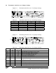

Table Of Contents

DANIELS
ELECTRONICS LTD
TM
3-8 CI-PM-3 Paging Modulator Instruction Manual
3.13 Repeater Configuration
The CI-PM-3 modules at both the base transmitter and paging/repeater must be configured
individually. Individual setup procedures must also be followed for analog/digital paging and for
digital-only paging.
Note: The CI-PM-3 modules must be set for 2-level signal operation only when configured for
use in a paging repeater system.
3.13.1 Base Transmitter Site CI-PM-3 Configuration
The setup instructions of sections 3.13.1 through 3.13.3 must be completed prior to commencing
setup of the remote paging/repeater site CI-PM-3. Jumper designators separated by a ‘/’ indicates
an ‘and/or’ selection (eg JU19/JU45 means JU19 and/or JU45).
3.13.1.1 Digital-Only Paging
1. Install shunt jumpers JU7-A, JU8-A, JU10-A, JU41-C and JU23-A, JU23-B or JU23-C.
2. Install surface mount jumpers JU22, JU55, and JU20/JU21.
3. Remove surface mount jumpers JU19, JU28, JU29, JU30, JU34, JU43, JU44, JU45, JU52,
JU53 and JU54.
3.13.1.2 Analog/Digital Paging
Ensure the TS-64 CTCSS Module, MOD1, is installed. Refer to section 3.13.3 for TS-64 CTCSS
Module Configuration and settings for jumpers JU52, JU53 and JU54.
1. Install shunt jumpers JU7-A, JU8-A, JU10-B, JU41-A and JU23-A, JU23-B or JU23-C.
2. Install surface mount jumper JU20/JU21, JU22 and JU55.
3. Remove surface mount jumpers JU19, JU28, JU29, JU30, JU34, JU43, JU44, JU45 and JU51.
3.13.2 Repeater Site CI-PM-3 Configuration
At the remote paging/repeater site, the digital paging signal is received and discriminated by the
receiver, regenerated (reshaped) by the CI-PM-3, and re-transmitted through the normal CI-PM-3
data signal path. Analog paging signals are routed from the receiver, through the CI-PM-3, then
directly to the transmitter.