
User's Manual


6
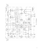
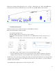
There are two jumpers (JP1, JP2) in the board – see Fig. 3. When JP1 is cut, “G/F” alarm LED at the
front panel is disconnected. When JP2 is cut, both “TX” and “VSWR” LED are disconnected.
Fig. 3
5. Installation Instruction.
The PA is intended to be installed in unique slot in the Daniels subrack.
Before the unit installation, make sure that:
- No mechanical damage exists
- The DC and RF connectors are clean (no dust or debris)
- Jumper JP1 and/or JP2 in DC Control Board is cut, if LED indication at the front panel is not
desired
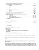
- 3-pin connector is in position, correct for the chosen power control method – see Fig.4;
Fig. 4 Fig.5
- DC cables, going to DC Connector board, are inside the unit outline;
- All four quick realease fasteners are in position: their screws shall be pushed into the plastic
cylinders and slots in heads of screws shall be directed horizontally, as it is showed in Fig. 5.
Provide the correct positioning of leading rails of PA and subrack, then slide PA all way through inside
a subrack. Press and turn screws of all quick release fasteners by 90° clockwise or counter clockwise,
until PA is fixed in subrack.
Connect RF cables to RF connectors at the front panel of PA.