
User guide


Charnwood Dynamics Ltd. Coda cx1 User Guide – Advanced Topics III - 2
CX1 USER GUIDE - COMPLETE.doc 26/04/04
98/162
USING VECTOR ANGLES
The methods described herein relate to the construction and interpretation of Vector Angles
as provided for within Codamotion Analysis software (‘Setup’ menu: ‘Define Angles...’).
A vector angle is the angle between two vectors (which we may visualize as straight lines).
Most users will be familiar with the notion of the angle between two straight lines on a flat
(2D) surface (extended to their point of intersection if necessary); not so many will have
tackled the more general concepts of vectors - directed straight lines in 3D space - which
almost certainly have no real point of intersection at which to measure the (3D) angle.
There is, moreover, a clear distinction between vectors we might call position vectors and the
more general, free vectors used to define vector angles. A position vector is, of course, a
vector quantity (having three ordered components representing both magnitudes and
directions), but one whose interpretation is anchored to the origin of a co-ordinate frame;
indeed the term ‘position vector’ is synonymous with ‘(3D) co-ordinates’.
The more general type of free vector, however, is not anchored to any origin and need not
necessarily correspond to a line between two points in space, although it still has the same
components representing magnitudes and directions. The relative orientation of any two
such vectors will give rise to a vector angle whose name we can choose and whose
definition can be saved in a Setup file. Any number of vector angles may be defined and
saved according to the following guidelines.
Defining two vectors
From the Setup menu choose ‘Define Angles...’, then ‘New Angle’. We are presented with
a comprehensive menu from which to choose the construction of the requisite free vectors.
In the present versions of the software there are limitations on the recipe used to define the
vectors. One must use either markers (or virtual markers) or segment reference points (of a
standard gait model), but not a mixture of both types.
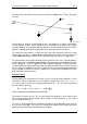
The first of our vectors is defined in one of two ways from markers or reference points in the
lists provided. The simpler option is to define the vector like a straight line between the first
two points chosen (they must, of course, be different). For example, two markers on the
index finger might define a vector to represent the direction in which the finger points, but
only if we are clear which way is positive. The positive sense of such a vector would be the
direction from the first marker to the second.
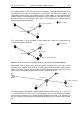
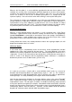
Alternatively one may select three, well separated points to represent a plane whose normal
(perpendicular to the plane) defines the vector. The positive sense of this normal vector
depends on the cyclic spatial order of the three points chosen (it is calculated as a ‘cross’
product of two vectors lying in the plane). For example, we might place three markers about
the cranium to define a head-orientation plane whose normal would define local (head)
vertical:
M
2
M
3
M
1