
User guide


Charnwood Dynamics Ltd. Coda cx1 User Guide - Gait Analysis II - 1
CX1 USER GUIDE - COMPLETE.doc 26/04/04
70/162
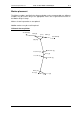
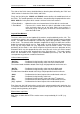
Thigh / Knee Joint
The thigh segment representation derives from a combination of data from the thigh wand
markers and femoral joint positions - the Knee joint, and the Hip joint (already obtained).
The Knee joint is modelled as a simple medio-lateral axis and as such is defined (at
present) by the Knee marker on the lateral aspect and a medially offset reference point on
the medial aspect, to be labelled ‘MedKnee’. The Knee marker position is elevated in
status to segment reference point ‘LatKnee’.
The medial offset for MedKnee is 1 knee width, w, (as found in Patient Data) from
LatKnee in a direction effectively equivalent to the perpendicular to the plane defined by
the cosmetic VirtualHip point and the two thigh wand markers. The VirtualHip point is
laterally shifted from the Hip joint by approximately half a knee width as are the real thigh
wand markers (‘Ant.Fem.’, ‘Post.Fem.’). The purpose of this adjustment to the thigh wand
plane is to align it more accurately with the femur for an improved perpendicular medio-
lateral knee axis.
The KneeCentre reference point is simply the mid-point of the so-defined knee axis.
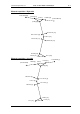
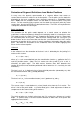
The Thigh EVB is constructed around the principal femoral ‘z’ axis defined between
HipJointCentre and KneeCentre. The thigh wand markers define the local x axis
following the Gram-Schmidt procedure applied with the principal axis already in place.
The local y axis follows with the cross product of u
x
and u
z
.
Thus:
P
latknee
= M
knee
P
medknee
= M
knee
+ wu´
y
(where u´
y
is the unit vector perpendicular to the ‘thigh-
lateral’ plane)
K
Centre
= ½ (P
latknee
+ P
medknee
)
u
z
= U
z
(H - K
Centre
)
u
x
= GS
x
(u
z
, M
AntFem
- M
postFem
)
u
y
= U
y
(u
x
, u
z
)
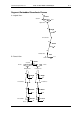
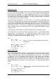
Shank / Ankle Joint
This segment representation follows a similar procedure to that for the thigh and knee
above. The principal axis of the tibia is defined between the KneeCentre (from above)
and the AnkleCentre which is taken to be the mid-point of the ankle axis. The ankle axis
is defined as the line extending medially from the Ankle marker with orientation
perpendicular to the shank-lateral plane (as defined by the Tibial Wand markers and the
line joining the Knee marker to the Ankle marker). The Tibial Wand local transverse
projection will define the shank-local x axis and the ankle axis is taken to be perpendicular
to that.
Thus:
P
latankle
= M
ankle
P
medankle
= M
ankle
+ wu´
y
(where u´
y
is the unit vector perpendicular to the ‘shank-
lateral’ plane)
A
Centre
= ½ (P
latAnkle
+ P
medAnkle
)
u
z
= U
z
(K
Centre
- A
Centre
)
u
x
= GS
x
(u
z
, M
antTib
- M
postTib
)
u
y
= U
y
(u
x
, u
z
)