FET PREAMPLIFIER 02b OPERATION MANUAL T E C H N O L O G I E S I N C .
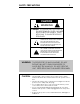
SAFETY PRECAUTIONS 1 CAUTION WARNING ! CAUTION: TO PREVENT ELECTRIC SHOCK, DO NOT REMOVE COVER. NO USER SERVICEABLE PARTS INSIDE, REFER SERVICING TO QUALIFIED SERVICE PERSONNEL. THIS SYMBOL IS TO ALERT YOU OF THE PRESENCE OF UNINSULATED DANGEROUS VOLTAGE WITHIN THE UNIT'S ENCLOSURE THAT MAY BE OF SUFFICIENT MAGNITUDE TO CONSTITUTE A RISK OF ELECTRIC SHOCK. ! THIS SYMBOL IS INTENDED TO ALERT YOU OF THE PRESENCE OF IMPORTANT OPERATING AND MAINTENANCE INSTRUCTIONS IN THE LITERATURE ACCOMPANYING THE UNIT.
INTRODUCTION 2 This preamplifier is a precision device, designed in an effort to provide the listener with unmatched sound quality, design, and construction. In order to operate your preamplifier properly and to realize all of the capabilities of the FET PREAMPLIFIER 02b, we recommend that you read this entire manual carefully.
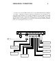
INSTALLATION CONNECTIONS 3 The first section of the installation instructions for the FET PREAMPLIFIER 02b is a diagram of the basic configuration required to bring the preamplifier into an operating mode. These brief steps will allow you to begin operating your system. Make sure during installation that the level control is turned fully counter clockwise, all other components are off, and AC power connections are interrupted to the preamplifier.
DETAILED INSTALLATION 4 I. Set up and Installation WARNING: NEVER OPERATE THIS UNIT WITH THE TOP COVER REMOVED. NEVER MAKE ANY INTERNAL ADJUSTMENTS WHILE THIS UNIT IS CONNECTED TO AN AC POWER SOURCE. 1. Position the FET PREAMPLIFIER 02b in the space which you have chosen, leaving enough space to connect the ancillary components of your audio system, and the AC power cord for the preamplifier.
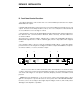
DETAILED INSTALLATION 5 II. Source-Output, and Power Connections The input and output connectors are clearly marked on the rear lip of the top cover. It is important to remember the correct left or right channel orientation. The function and channel markings on the rear panel correspond to the front panel controls and their signal paths. They are: 1. The BALANCED DISC inputs should be attached to the balanced outputs of a compact disc player or phono stage.
DETAILED INSTALLATION 6 III. Front Panel Control Functions 1. The INPUT SELECTOR control selects the source which will be presented to the outputs and balanced outputs. 2. The RECORD SELECTOR control selects the source which will be presented to the record output. Because of the independent controls, one source may be monitored while a second, different source is being recorded. 3.
DESIGN PHILOSOPHY 7 I. Design Philosophy and Approach The circuitry utilized in the FET PREAMPLIFIER 02b is the result of an advanced and complete design process combining innovation and proven fundamentals. This process avoids both the limitations of total adherence to convention and the flaws resulting from inappropriate application of clever circuit gimmicks. Our approach demands painstaking consideration of every facet of each design choice regardless of how small.
DESIGN PHILOSOPHY 8 The requirements of a power supply for flawless audio reproduction are straightforward but important. The supplies in the FET PREAMPLIFIER 02b take a very direct approach to high performance. First, a top quality shielded toroid transformer with plenty of reserve current capability is used. About 28,000 uF of capacitance with very low ESR and inductance provides good passive filtering. A reference voltage is developed by delivering a constant current to zener diodes.
DESIGN PHILOSOPHY 9 II. Parts' Quality 1. Finishes - All exterior and interior metal parts are anodized. While paint may be more impact resistant, the anodized surface is more resistant to solvents and prevents corrosion. Moreover, the anodized parts' appearance can be enhanced by either graining or bead-blasting the surface. 2. Circuit Board - Circuit boards are fiberglass epoxy with gold plating over a tin/nickel barrier.
TECHNICAL DATA 10 CIRCUIT SPECIFICATIONS Frequency Response: Distortion: DC to -3 dB @ 200 kHz < .01 % from 10 Hz to 40 kHz @ 6V peak into 600 Ohms or higher, shunted by 1000 pF or less .
CARE and HANDLING 11 The interior of the unit requires no special care, due to the use of sealed controls and gold plating on contacts. If it becomes necessary to clean the exterior, a simple dusting may be all that is required. If a cleaner is necessary, any dilute commercial ammonia based product will be appropriate. NEVER use any abrasive rags, cleaners or chemical solvents on the preamp. When handling the unit, take care not to mar the aluminum.
WARRANTY 12 I. Warranty- Any failure of the FET Preamplifier 02b to operate or to meet specifications, applicable at time of manufacture, due to a manufacturing defect or component failure, will be corrected by Coda Technologies, Inc. without charge for parts, or labor for a period of ten years from date of original purchase. Coda Technologies, Inc. will provide for surface transportation to and from the factory from an authorized Coda Technologies, Inc.
WARRANTY REGISTRATION Fill in and retain this copy of the warranty registration sheet for your records .
WARRANTY REGISTRATION 13.5 Please fill in and send this copy of the warranty registration sheet to Coda Technologies, Inc. Include copy of proof of purchase.
ADDRESS Coda Technologies, Inc.