Cochlear™ Clinical Guidance Document
CLINICAL GUIDANCE | TABLE OF CONTENTS SECTION 1 : PROGRAMMING PRINCIPLES 1.1 STREAMLINED PROGRAMMING METHODS 1.1.1 Behavioural Procedures 1.1.2 NRT/Objective Offset Method 1.1.3 NRT/Objective Preset Method 6 7 8 10 1.11 MICROPHONE SENSITIVITY AND VOLUME SETTING 34 1.11.1 Microphone Sensitivity 34 1.11.2 Volume Setting 35 1.2 ADJUSTMENTS TO CHANNEL GAINS 12 1.12 NUCLEUS® SMARTSOUND™ 1.12.1 ADRO® 1.12.2 Whisper™ 1.12.3 Focus (using Beam) 1.12.4 Zoom 36 36 37 39 43 1.13 SMARTSOUND ENVIRONMENTS 46 1.
SECTION ONE | CLINICAL GUIDANCE The primary aim of programming a sound processor is to customize the device so that the cochlear implant provides comfortable and usable stimulation to a recipient. A clinician uses the programming software to deliver electrical stimulation and measure patient-specific psychophysical parameters. This Cochlear™ Clinical Guidance Document provides information to assist in understanding clinical programming practices.
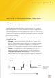
CLINICAL GUIDANCE | SECTION ONE SECTION 1 : PROGRAMMING PRINCIPLES Getting started At the initial activation, the clinician uses Custom Sound™ to program the sound processor so that the cochlear implant system delivers sound that is audible and comfortable to the cochlear implant recipient. The streamlined programming methods in Custom Sound help the clinician by simplifying the programming procedure and reducing programming time.
SECTION ONE | CLINICAL GUIDANCE • Current Level (CL) – the amount of electrical current delivered to the implant recipient expressed in clinical programming units from 1 – 255. Current Levels represent the amplitude of the biphasic current pulse in microamperes (µA) on a log scale similar to dB (5.7 CL = 1 dB). The amplitude range of the cochlear implant stimulator is 10 µA - 1.75 mA (see Figure 1 on page 3).
CLINICAL GUIDANCE | SECTION ONE The remaining T-levels are automatically interpolated. If you wish to measure other channels, simply double-click on the specific channel or click the “make all channels measurable” button to access the entire array. • C-level – Comfort Level – the maximum level of stimulation in CL that does not produce uncomfortably loud sounds (the level that is as loud as a recipient could listen to comfortably for long periods).
SECTION ONE | CLINICAL GUIDANCE 1.1 STREAMLINED PROGRAMMING METHODS Custom Sound includes three streamlined programming methods that make programming simpler for the recipient and reduce programming time without compromising outcomes (preliminary data collected at the Cooperative Research Centre for Cochlear Implant and Hearing Aid Innovation in Melbourne1 and in the US Streamlined Programming Study).
CLINICAL GUIDANCE | SECTION ONE 1.1.1 Behavioural Procedures 1. Measure impedances by performing an implant test. 2. In the Open or Create MAP screen, create a new MAP by selecting the required MAP parameters from the available drop-down menus and clicking Create. Alternatively, you can select and open an existing MAP that you can modify. The default streamlined programming method is the behavioural one and by default, channels 22, 16, 11, 6, and 1 are highlighted for measurement.
SECTION ONE | CLINICAL GUIDANCE 1. Stop the stimulation and sweep all of the channels at 80% and then at C-level to confirm that sounds are comfortably loud. (Open the Sweep menu by clicking on the Sweep drop-down menu.) You can balance loudness across the channels by sweeping a small set of channels (4 – 5 at a time) to confirm equal loudness.
CLINICAL GUIDANCE | SECTION ONE 4. The default streamlined programming channels 22, 16, 11, 6, and 1 are highlighted. In the Method box, click the “Select NRT/Objective Levels” button. Select the measurement type (e.g. NRT), the values you wish to use from the “date of measurement” and click ok (more than one set of measurements may be selected.). This brings the T-NRT values (blue markers) on the measured channels into the Set Levels screen.
SECTION ONE | CLINICAL GUIDANCE 1.1.3 NRT/Objective Preset Method The NRT/objective preset method offsets the T- and C-level profiles from the objective measurement profile. Additional MAPs are created with the C-levels set progressively higher on each MAP. This method is appropriate for very young children or others who may not give any reliable behavioural responses. 1. Measure impedances by performing an implant test. 2.
CLINICAL GUIDANCE | SECTION ONE where T-NRT fell in relation to the behavioural dynamic range. As a result of the large variability between recipients, offsets may need to be changed depending on the stimulation rate being used for the MAP. The current C-level offsets in Custom Sound may result in MAPs that are too soft for some recipients when using the higher stimulation rates. 8.
SECTION ONE | CLINICAL GUIDANCE 1.2 ADJUSTMENTS TO CHANNEL GAINS In addition to the user-controlled microphone sensitivity that determines the overall gain applied to the input signal, each channel in the MAP includes an adjustable gain control. These individual channel gains are set in the MAP when the clinician programs the sound processor. The default gain setting is 0 dB across all channels.
CLINICAL GUIDANCE | SECTION ONE • Automatic Gain Control (AGC) – front-end amplifier that reduces the gain of high amplitude inputs to avoid distortion/peak clipping. The AGC threshold depends upon the microphone sensitivity setting. • Autosensitivity – this algorithm automatically adjusts the microphone sensitivity to lessen the effects of background noise. 1.3.
SECTION ONE | CLINICAL GUIDANCE 1.3.2 Supported Combinations of Implant System Components The supported combinations of implant system components and programming systems for Custom Sound 3.2 approved for all regions, are summarized in the following table.
CLINICAL GUIDANCE | SECTION ONE 1.4 ELECTRICAL STIMULATION AND MAP PARAMETERS • Stimulation Mode – describes the location of the indifferent electrode relative to the active electrode. • Stimulation Rate – the frequency (Hz) of the biphasic current pulse delivered to a channel. The clinician uses the software defaults or alternatively selects a stimulation rate. • Total Stimulation Rate (TSR) – the rate across the entire electrode array for a stimulation cycle.
SECTION ONE | CLINICAL GUIDANCE • IIDR (Instantaneous Input Dynamic Range) – is the selected range of input signal at any instant in time that will be mapped between T- and C-level, i.e. the audible range of sounds for a recipient. It is a programmable value determined (in Freedom and CP810 sound processors) by two MAP parameters, T-SPL and C-SPL. It is the dB difference between the two. For example, at the default microphone sensitivity of 12, for a T-SPL of 25 and C-SPL of 65, the IIDR is 65 - 25 = 40 dB.
CLINICAL GUIDANCE | SECTION ONE 1.5 STIMULATION MODES Electrical stimulation produces current flow between an active (stimulated) and indifferent (reference) electrode. A pair of electrodes forms a channel of stimulation. For each channel, stimulation mode describes the location of the indifferent electrode relative to the active electrode. The distance between the two electrodes determines the spread of electrical current and the nerve endings or spiral ganglia that are stimulated.
SECTION ONE | CLINICAL GUIDANCE 1.5.2 Bipolar (BP) Stimulation In BP stimulation, both the active and indifferent electrodes are inside the cochlea. The separation between the two electrodes defines the BP configuration and the spread of current within the cochlea (see Figure 3). The smaller the distance between the active and indifferent electrodes, the more current required to reach T- and C-levels, probably because a smaller amount of neural tissue is stimulated.
CLINICAL GUIDANCE | SECTION ONE 1.5.3 Variable and Pseudomonopolar (PSMP) Stimulation Variable and pseudomonopolar stimulation modes combine different BP modes in the same program or MAP. For example, in variable mode some channels may be programmed in BP1 and others in BP2, BP3, or BPx. Variable mode can be used to increase the number of active channels in situations where there are a reduced number of electrodes available due to electrode anomalies or non-auditory sensations.
SECTION ONE | CLINICAL GUIDANCE Figure 4 : Common Ground stimulation Selecting the stimulation mode The clinician sets the stimulation mode in the Custom Sound software on the “Open or Create MAP” screen. The software lists the stimulation modes that are available based on the implant type, sound processor and sound processing strategy being used. The software defines the stimulation mode using the location of the indifferent (reference) electrode relative to the active (stimulated) electrode.
CLINICAL GUIDANCE | SECTION ONE • Out of Compliance – the condition where the maximum voltage available from the implant is not sufficient to generate the desired current level (CL) on a given channel. When this occurs, the implant recipient does not perceive loudness growth when the CL is increased, i.e. there is loudness saturation. • NRT – Neural Response Telemetry - records neural activity within the cochlea in response to electrical stimulation from the implant.
SECTION ONE | CLINICAL GUIDANCE Increasing the pulse width may result in the number of maxima being reduced automatically. The 3500 Hz per channel stimulation rate only allows a pulse width of 9.6 µs. It is important to optimize a recipient’s power level to ensure that all channels are in compliance, to allow the widest range of MAP parameters to be used for a given recipient, and to maximize sound processor battery life.
CLINICAL GUIDANCE | SECTION ONE required programming changes. Note: Nucleus 24 system implant recipients may upgrade to the CP810 or Freedom processor regardless of their current sound processor type. 1.7.3 Nucleus® 22 System The Nucleus 22 System does not include a telemetry function. For recipients using the CI22M implant (i.e.
SECTION ONE | CLINICAL GUIDANCE The power level required is dependent on the type of MAP, its various parameters, and the individual recipient. Power optimization selects the most appropriate power level for the recipient and each MAP and this is shown as a percentage (ranging from 0 - 100%). In general, a MAP with a higher stimulation rate or higher current levels requires a higher power level (for example, Custom Sound™ may specify a power level of 97% to effectively run such a MAP).
CLINICAL GUIDANCE | SECTION ONE If the coil is not on the implant when power optimization occurs, the power level is set to the previously saved level (where available) or the default manual level. Note: When the power level is optimized, a stimulation occurs which may be heard by the recipient.
SECTION ONE | CLINICAL GUIDANCE Before sending the recipient home, it is recommended that you determine the batteries that are best to use with the recipient’s MAPs. Freedom sound processors (Nucleus 22 implants) Custom Sound prompts you to measure the skin flap and optimize the power level when you first Go live with a MAP, Click Batteries in the Battery Suitability box or Write a program to the sound processor.
CLINICAL GUIDANCE | SECTION ONE The recipient does not hear this stimulation. For MAPs that are personalized for different listening environments, provided that the current levels, MAP stimulation rate, channel pulse width and mode are the same as the first optimized MAP, Custom Sound does not perform additional measurements. The power level is set to the same level as the first MAP.
SECTION ONE | CLINICAL GUIDANCE Table 1: The differences between SPEAK, CIS/CIS (RE) and ACE/ACE (RE) Strategy No. of Stimulation rates stimulation per channel (Hz) sites No. of maxima / channels stimulated per frame SPEAK 20 250 6 to 10 CIS/CIS (RE) 4, 6, 8 or 12 900, 1200, 1800, 2400 or 3500 4, 6, 8 or 12 (up to 8 for 1800, 2400, 3500 Hz ACE/ACE (RE) 22 250, 500, 720, 900, 1200, 1800, 2400 or 3500 up to 20 (depending upon stimulation rate selected) 1.9.
CLINICAL GUIDANCE | SECTION ONE Figure 5 : Electrodogram of the English word “choice” using the ACE strategy 1.9.2 SPEAK SPEAK (Spectral Peak) focuses on the spectral (frequency) properties of sound. It takes advantage of the 22 closely spaced intracochlear electrodes and the place pitch selectivity of the cochlea. The sound processor examines the ongoing acoustic signal and sends stimulation pulses to the appropriate electrode sites or channels based on the signal’s spectral content.
SECTION ONE | CLINICAL GUIDANCE The selected channels receive sequential stimulation in tonotopic order from high to low frequency. SPEAK uses a stimulation rate of 250 pulses per second (pps). The total stimulation rate (TSR) across the array is 2,000 pps for eight maxima and 2,500 pps for 10 maxima. SPEAK cannot currently be used with the CP810 Sound Processor unless accessed as a regional option in the Custom Sound™ software. Figure 6 illustrates the spectrogram (i.e.
CLINICAL GUIDANCE | SECTION ONE 1.9.3 CIS/CIS (RE) CIS (Continuous Interleaved Sampling) focuses on the temporal (timing) properties of sound. It uses a relatively small number of channels (4, 6, 8 or 12) in comparison to SPEAK and stimulates them at a high per channel rate. Higher stimulation rates better represent the rapid timing events in sound compared to lower rates. By default, the software chooses a fixed set of 12 channels and a 900 pps channel rate (TSR = 10800 pps).
SECTION ONE | CLINICAL GUIDANCE Figure 8 illustrates the electrical stimulation pattern of the English word ‘choice’ using a 6-channel CIS strategy. In this example, density of the striations represents the rapid temporal changes in the signal. Since CIS always stimulates the same channels, it does not convey frequency changes that occur in the signal. 1.
CLINICAL GUIDANCE | SECTION ONE When programming a Nucleus® 24 implant and the SPrint processor with 20 active channels, the default is Table 8 (188 - 7938 Hz) and the available nondefaults are Table 1-7. Changing to Table 6 reduces the input range to 188 6063 Hz. For the ESPrit 3G the default input frequency range reduces as the number of channels is reduced. However, other table numbers are available to further modify the input frequency range.
SECTION ONE | CLINICAL GUIDANCE 1.11 MICROPHONE SENSITIVITY AND VOLUME SETTING 1.11.1 Microphone Sensitivity The setting of the microphone sensitivity control determines the minimum input signal level required for stimulation. At higher sensitivity settings, less acoustic energy, i.e. a lower SPL, is required to cause stimulation. At lower sensitivity settings, greater acoustic energy, that is a higher SPL, is required to cause stimulation (see Figure 9).
CLINICAL GUIDANCE | SECTION ONE softer speech sounds. In both cases, C-levels should be re-assessed. The Sensitivity Mode may be set to ‘Manual’ or ‘Fixed’. When set to the ‘Manual’ mode the recipient can manually adjust the sensitivity setting by pressing the appropriate buttons on the Freedom™.
SECTION ONE | CLINICAL GUIDANCE With the CP810 Sound processor, the clinician can lock out the ability to change both sensitivity and volume via the Remote Assistant. Using Custom Sound software, the clinician can choose to allow the recipient to have access to sensitivity only, volume only, both sensitivity and volume, or neither option on their Remote Assistant. Other processors have volume controls (SPrint and ESPrit series).
CLINICAL GUIDANCE | SECTION ONE The channel gains adapt so as to optimize the loudness of the signal into the recipient’s dynamic range. For low intensity sounds, the gain is increased while for high intensity sounds, the gain is reduced to keep the signal level below the C-level (see Figure 10). The channel gains are adaptively adjusted to maintain the signal in each channel within the upper region of the dynamic range of hearing. ADRO responds slowly and smoothly to changes in signal level.
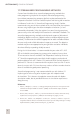
SECTION ONE | CLINICAL GUIDANCE 80 Whisper boosts soft sounds but not loud sounds Figure 11 : Input/ output functions of the standard microphone setting (dashed line) and when Whisper is enabled (solid line) referenced to a 1 kHz sine wave. Processed Signal (dB SPL) 70 AGC operating 2:1 60 50 1:1 40 30 20 20 30 40 50 60 70 80 90 Input Signal (dB SPL) Whisper may not provide significant benefit to all recipients in all environments.
CLINICAL GUIDANCE | SECTION ONE Figure 12: Speech perception scores with Nucleus Freedom. Whisper is used alone and in combination for the SmartSound Everyday environment and also in combination for the SmartSound Music environment. See section 1.13 SmartSound for more information. References 1. McDermott, H.J., Henshall, K.R., McKay, C.M. (2002). Benefits of syllabic input compression for users of cochlear implants. J AmAcad Audiol. 13, 14-24. 2. Cochlear Limited. (2002).
SECTION ONE | CLINICAL GUIDANCE Focus with the Freedom Sound Processor The Freedom sound processor implements the beam algorithm using one dual port directional and one omni-directional microphone. The beamformer output is formed by combining the signals from two microphones, the directional microphone at the front of the sound processor and the omnidirectional microphone at the rear of the processor. There are two stages to the adaptive beamformer (see Figure 13).
CLINICAL GUIDANCE | SECTION ONE Figure 14: Examples of sensitivity plots for Beam (light blue line) and a fixed directional microphone (dark blue line) The polar plots in Figure 14 compare the directional sensitivity of Beam (light blue line) and a fixed directional microphone (dark blue line) for noises coming from different directions. On the plots, 0° corresponds to in front of the listener, 90° to the left, 180° behind and 270° to the right.
SECTION ONE | CLINICAL GUIDANCE The effects of Beam were evaluated in a double-blind trial with five adult Nucleus® CI users4. Subjects were tested with their standard program and were then fitted with Beam. Testing with Beam was carried out after a twoweek trial period. Speech Reception Threshold (SRT) with sentences and the percentage correct phoneme scores for Consonant-Vowel-Consonant (CVC) words were measured in quiet and noise at different signal-to-noise ratios.
CLINICAL GUIDANCE | SECTION ONE Group mean results for CUNY sentences at 65dB SPL are shown in Figure 16, and indicate a statistically significant mean improvement of 12 percentage points with CP810 (67%) over the Freedom sound processor (55%) when Focus (using Beam) was enabled.
SECTION ONE | CLINICAL GUIDANCE equally, so a null position is selected to give the best overall result. With zoom, this null direction is fixed (Figure 17). Zoom provides more moderate noise cancelling compared to Beam and is recommended for generally noisy places or for situations where the noise is stationary and the listener can move such that the noise source is behind him. It is not recommended for use in quiet or windy environments.
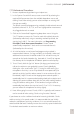
CLINICAL GUIDANCE | SECTION ONE Testing in noise with zoom (n=15) Freedom No Zoom CP810 No Zoom CP810 Zoom Figure 18: Improvement of speech perception scores in noise with CP810 using Zoom compared with CP810 and Freedom using standard microphone directionality (no Zoom).
SECTION ONE | CLINICAL GUIDANCE Recommendations for changing Autosensitivity (ASC) breakpoint Increasing the Autosensitivity breakpoint will make it less aggressive / prevent it from turning down the sensitivity so much. Decreasing the Autosensitivity breakpoint will make it turn down the sensitivity more. It is not recommended to change both the Autosensitivity breakpoint and the base level (for the ESPrit 3G processor).
CLINICAL GUIDANCE | SECTION ONE Environment Options Everyday This environment is used in typical listening situations. A clinician will typically program this in P1 and instruct the recipient to use this setting most of the time. It can be modified for recipients whose listening environments are particularly loud or soft. • CP810 SOUND PROCESSOR OPTIONS Autosensitivity™ + ADRO® – Autosensitivity minimizes the effects of noise in the changing acoustic environment.
SECTION ONE | CLINICAL GUIDANCE FOCUS This environment is used when there is significant background noise, but the focus is on hearing what one person, or a small group of people are saying. A clinician will typically program this in P3 and instruct the recipient to use this setting when listening to sounds right in front while in a noisy place. • CP810 SOUND PROCESSOR OPTIONS Beam™ + Autosensitivity + ADRO – This environment uses adaptive directional hearing.
CLINICAL GUIDANCE | SECTION ONE When you convert a Freedom MAP to a Nucleus 24 MAP, input processing options that are not supported on Nucleus 24 sound processors will not be available. Similarly, when you convert a CP810 MAP to a Freedom or Nucleus 24 MAP, input processing options (e.g. Noise with zoom) that are not supported on Freedom or Nucleus 24 processors will not be available. 1.14 Objective Measurements 1.14.
SECTION ONE | CLINICAL GUIDANCE • Alternating stimulus polarity will effectively reduce the stimulus artefact. However, there may be a disadvantage if the evoked brainstem responses from negative and positive leading stimulus pulses have different response latencies. This can be reduced by using narrow pulse widths, for example, 25 μs. (Absence of an EABR does not mean that the implant is not working or that the individual will not stimulate postoperatively.) 1.14.
CLINICAL GUIDANCE | SECTION ONE Absence of ESRT does not mean the implant is not working or the recipient is not hearing. There can be other causes for the absence of the response, such as middle ear disease. 1.15 Guidance for FM Fittings 1.15.1 CP810 Sound Processors FM systems are designed to improve a recipient’s signal to noise ratio (SNR) to allow them to hear better in noise. They are useful when the signal comes from a consistent source.
SECTION ONE | CLINICAL GUIDANCE Accessory Adaptor. The Freedom Accessory Adaptor is needed to connect the processor end of the ESPrit FM cable into the accessory socket of the CP810 Sound Processor. The body-worn FM receiver is used in combination with an FM transmitter and microphone, which picks up the speaker’s voice.
CLINICAL GUIDANCE | SECTION ONE Parameter Auto Telecoil Recommendation Off. (Note: for neckloop receivers, please activate the telecoil) SmartSound Environment ASC+ADRO (use default Everyday Environment setting and the default sensitivity setting of 12) Rationale Cochlear recommends deactivating Auto Telecoil for children.
SECTION ONE | CLINICAL GUIDANCE Many factors impact the battery life of a sound processor including the use of some accessories. It is important to note that ear-level FM receivers that require the use of the Euro Accessory Adaptor are active devices (i.e. they draw power from the CP810 Sound Processor, unlike other accessories such as the personal audio cable which is not an active device).
SECTION TWO | CLINICAL GUIDANCE CLINICAL GUIDANCE | SECTION TWO SECTION 2: PROGRAMMING RECOMMENDATIONS FOR SPECIALTY DEVICES 2.1 SPECIALTY DEVICES 2.1.1 ABI The Nucleus® 24 ABI (Auditory Brainstem Implant) is functionally very similar to the Nucleus 24 cochlear implant and uses the same receiver/stimulator (Figure 1).
SECTION TWO | CLINICAL GUIDANCE Figure 2: Descriptive illustration of the Nucleus 24 ABI 2.1.1.1 Setting Up the ABI Equipment Before switch-on • Since tuning the Nucleus 24 ABI is time-consuming, consider scheduling the recipient for programming over two to three days. The underlying medical condition might also mean individual sessions need to be short. • Counsel the recipient about the tuning procedure and assess their expectations.
CLINICAL GUIDANCE | SECTION TWO ECG monitoring equipment Caution: During stimulation the recipient must be connected to ECG monitoring equipment with a member of medical staff qualified in resuscitation present. Due to the proximity of the auditory brainstem implant electrodes to the tenth nerve (vagus), there is a small risk that electrical stimulation could disturb heart rhythm. A standard 3-lead ECG is sufficient to monitor heart activity.
SECTION TWO | CLINICAL GUIDANCE Figure 3: Positioning the retainer disk 7. Position the transmitter coil so it is just below the retainer disk. The transmitter coil will then be located directly over the receiver coil. 8. Re-apply retainer disks every one to three days as required. Finding the receiver/stimulator To find the receiver/stimulator: 1. Palpate the area or check for a tattoo, (if used). 2. Use Custom Sound software to connect to the receiver/stimulator. 3.
CLINICAL GUIDANCE | SECTION TWO Performing Psychophysics Note: It is important that you perform psychophysics on an electrode-byelectrode basis. Interpolation or streamlined fitting is not appropriate for an ABI due to variation in T- and C-levels from one electrode to the next, even when using monopolar mode. Default parameters Cochlear recommends using the SPEAK strategy for the initial programming session, as it allows the use of wider pulse widths and has a lower rate of stimulation.
SECTION TWO | CLINICAL GUIDANCE Scenario One In the best case scenario, all channels would have both T-levels and C-levels below any side-effect threshold (Figure 4). Figure 4 : Best case ABI programming scenario Scenario Two In the worst case, it is impossible to find T-levels and C-levels since they are above the threshold of a side effect on all channels (Figure 5).
CLINICAL GUIDANCE | SECTION TWO Scenario Three In a typical case, there is usually a group of channels which has only side effects, another which has only auditory sensations, and a further group which has a side effect which presents between T- and C-level (Figure 6). Figure 6 : Typical ABI programming scenario It is recommended that you investigate C-levels on all possible channels before attempting to find accurate T-levels.
SECTION TWO | CLINICAL GUIDANCE Table 1: Loudness/sensation strength scale Auditory Sensation Scale Side Effect Stop 10 Stop Too loud 9 Uncomfortable sensation Maximum comfortable level 8 Very loud 7 Loud 6 Medium loud 5 Medium 4 Quiet 3 Very quiet 2 Just hearing 1 Very slight sensation No sound 0 No sensation Strong sensation Medium strong sensation Mild sensation Exceeding safe levels of stimulation Caution: In Current Level modulation, when stimulus pulse widths exceed 200
CLINICAL GUIDANCE | SECTION TWO What to do if you reach the safe limit level The levels listed in the table below are considered to be conservative values of the stimulation safe limit, i.e. they are significantly below levels at which damage has ever been observed in neural tissue. These boundaries should, however, be treated with caution, and as suggested below.
SECTION TWO | CLINICAL GUIDANCE Table 3: Maximum safe current and corresponding current levels for various stimulus pulse widths for the Nucleus ABIM implant Pulse width (µs) Maximum safe Current Level (CL) 25 50 100 150 200 250 300 350 400 >255 >255 >255 >255 255 244 235 227 221 The above table shows that up to pulse widths of 200 µs, the full stimulator output (255 units) may be safely used.
CLINICAL GUIDANCE | SECTION TWO For supplementary programming guidelines for the Nucleus Freedom Processor for Nucleus 24 ABI (ABI24M) using Custom Sound 2.0 or Custom Sound 3.0, please contact your Cochlear representative. 2.1.1.3 Managing Side Effects • Investigate narrower bipolar combinations, which either use or traverse electrodes giving auditory sensations in monopolar mode (if any), especially where these sensations have the largest dynamic range.
SECTION TWO | CLINICAL GUIDANCE 2.1.1.4 Fine Tuning the ABI Balancing/sweeping Before carrying out any pitch perception test, it is important to balance the loudness of all functional channels. To achieve this, first balance at C-level, and then at 50% of the dynamic range. • Balancing at C-level – Use the Sweep option to stimulate pairs/groups of channels at C-level, making adjustments as appropriate. Always use one balanced channel as a reference for the next one.
CLINICAL GUIDANCE | SECTION TWO Give clear instructions to the recipient before conducting the pitch-ranking procedure to ensure they understand the task is to rank pitch and not loudness. 1. (Optional) Sweep across all active channels to find two channels that are clearly distinct by pitch (e.g. approximate lowest and highest) as this can make the pitch ranking task easier. 2. Select the two channels you wish to compare by clicking on the channel number until it changes to yellow. 3.
SECTION TWO | CLINICAL GUIDANCE 11.It is strongly advised that after every few channels have been added to the ordered list, to sweep all the ordered channels to check no channel is incorrectly positioned. 12.In practice, recipients will usually find some channels that are so close in pitch to another channel that they cannot easily be distinguished.
CLINICAL GUIDANCE | SECTION TWO a better subjective impression between MAPs. Once you select a favourable MAP, encourage the recipient to use the processor as much as possible. It is not recommended to give the recipient many different MAPs at a first programming session. 2.1.1.5 Follow up Programming Optimal sound processor tuning for Nucleus 24 ABI recipients is a complex process and will involve many return visits to the clinic.
SECTION TWO | CLINICAL GUIDANCE 2.1.1.
CLINICAL GUIDANCE | SECTION TWO Note: It is recommended to maximize perceptual abilities wherever possible. This is because ABI performance is generally low at first. To MAP an ABI recipient: 1. To find the receiver / stimulator, palpate the area or check for a tattoo (if used). 2. Use Custom Sound to connect to the receiver / stimulator. 3. If the recipient has no internal magnet, start testing with a headband, and then shave the scalp for the retainer disk. 4.
SECTION TWO | CLINICAL GUIDANCE 2.1.2 The Nucleus® 24 Double Array The Nucleus® 24 Double Array (CI 11+11+2M) cochlear implant is based on the Nucleus 24 (CI24M) cochlear implant. The receiver/stimulator and reference electrodes are identical to those of the Nucleus 24. The electrode array is split in two parts, a basal array for insertion into the basal turn of the scala tympani and an apical array for insertion into the apical turn of the scala tympani.
CLINICAL GUIDANCE | SECTION TWO Prior to programming, check with the surgery report to confirm which electrode array is in which turn of the cochlea and whether the orientation is standard or retrograde, as this will affect electrode-to-channel allocation. 2.1.2.1 Programming the Double Array The Nucleus 24 Double Array can be programmed in the same modes as the Nucleus 24 (CI24M) except for common ground. However, it is recommended to use MP1+2 where possible as this will result in lower T- and C-levels.
SECTION TWO | CLINICAL GUIDANCE To ascertain electrode location (base or apex): 1. Select one active electrode mid-way along each array (e.g. 6 and 17 with a full insertion of both arrays) using the channel check tick boxes. Use the ‘Balance’ function to stimulate the two electrodes and deactivate all remaining electrodes. If the electrode array is inserted as recommended, pitch should decrease with increasing electrode number. Electrode arrays that have been switched (i.e.
CLINICAL GUIDANCE | NOTES 75
As the global leader in hearing solutions, Cochlear is dedicated to bringing the gift of sound to people all over the world. With our hearing solutions, Cochlear has reconnected over 200,000 people to their families, friends and communities in more than 100 countries. Along with the industry’s largest investment in research and development, we continue to partner with leading international researchers and hearing professionals, ensuring that we are at the forefront in the science of hearing.