
Troubleshooting guide

SPYBALL 6808-9/6828-9 ENGLISH 15
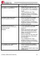
WHITE/GREEN
wires
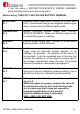
N. 12
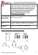
Second ignition immobilisation circuit. Cut the positive
cable that powers the starter solenoid. Connect one
end to one of the wires , the other end to the other wire.
During the cranking phase, measure the value of
the electrical current in the circuit that has been
cut, to make sure that it does not exceed the
technical specifications of the product.
Install an additional relay if necessary.
6808 – 6809 = DO NOT USE;
RED and BROWN
wires with a 2-
way connector
Connect to the pre-wired LED that comes with the
alarm fitting accessories;
WHITE/RED wire
N. 13
This wire supplies a trigger control during the alarm
phase. It allows for the connection of e.g. BikerSat;
BLACK wire
Antenna
Do NOT cut or ground the antenna wire!
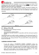
Engine immobilisation application diagram (B)