
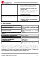
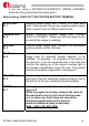
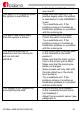
Troubleshooting guide

SPYBALL 6808-9/6828-9 ENGLISH 13
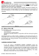
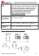
Once all connections are completed, secure the unit firmly, by means of the
supplied bolts and nuts and/or fitting wings, as appropriate for each specific
application (see also picture A underneath).
Always fit the red round rubber gaskets (vibration absorbers) between the
fitting wings and/or the bolt heads and the surface the unit is in touch with). If
the unit is placed on a flat surface, you can use adhesive velcro tape (not
supplied).
ILL. A
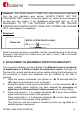
2.1. Siting of the LED
The LED performs the following functions:
- visual deterrent
- visual indication of alarm status
- emergency override function in conjunction with the motorcycle ignition
switch.
It should be sited in a visible location, preferably on the instrument board. To
fit the LED, drill a 10mm hole, ensuring that the panel is free from obstruction
and protecting any wiring enclosed. The pre-wired LED is then pushed fully
home into the hole.
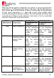
3.WIRING INSTRUCTIONS
- If you are using a STANDARD WIRING HARNESS, follow the
instructions herebelow. All the connections should be soldered and
insulated. Remark: the cable harness is available with multi-colour wires
or with one-colour numbered wires (the small numbers printed at the
ends of the wires have to be removed upon installation). The table
herebelow shows both the colours and the numbers.