
Service manual


3
M
e
ss
a
g
e
s in Cod
e
The actual message in each box consists of just eight numbers, each of which can be "1" or
"0".
So a typical message might be
1 1 0
1 0
0 0 1
This you will
recognise as precisely the same
sort of code which a channel switch supplies
to a PLL in order to select a channel.
The number of each box can also be represented as a code.
For instance:-
the first box may be numbered
0 0 0 0 0 0 0 0 0 0 0 1
and the second box could be
0 0 0 0 0 0 0 0 0 0 1 0
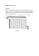
In practice, the box LOCATION NUMBER is applied to the
Eprom input pins as high or
low voltages representing "1" or "0".
The CONTENTS of the selected box
appear on the eight
Eprom
output pins as high or low
voltages.
For instance:-
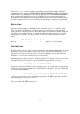
A11 A10 A9 A8 A7 A6 A5 A4 A3 A2 A1 A0
inputs
box number- 0 0 0 0 0
0 1 0 1 0 1 0
might have the
D7 D6 D5 D4 D3 D2 D1 D0
outputs
contents- 1 1
1 0 1 0
0 1
As the LOCATION NUMBER of each box is applied to the input pins, so the CONTENTS
of that box appear as voltages on the 8 output pins.
S
e
l
e
ct
a
Ch
a
nn
e
l
Suppose we connect the
Eprom between the channel selector switch and the PLL.
Normally, the code from the switch will tell the PLL which channel to select but now we
have altered things.
The code from the switch is seen by the
Eprom to be a LOCATION NUMBER for a box.
The
Eprom puts the CONTENTS of this box on its output pins. The PLL sees a channel
code which is DIFFERENT from the switch code and is "fooled" into producing the wrong
channel!