
Service manual


29
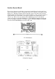
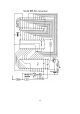
Anoth
e
r Eprom Bo
a
rd
The previous design was specifically for certain rigs but this
Eprom board for the Cobra
may be used with most versions. Six pull-up resistors are connected to the channel switch
inputs O to 5, which are arranged exactly in the right order for the ribbon cable from the
channel switch itself.
Eprom inputs A6 to A10 are available to select several more bands, if
required. However, no more than 5 volts must be applied to these inputs unless series
resistors (e.g. 10k for +9v) are connected. The eight pull-up resistors on the
Eprom
outputs are required for the MC145106P but not for the MB8719 which has internal pull-
ups. If you fit them, connect the
9 volt input to pin 18 of the MC145106P. Note that this
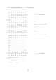
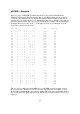
board uses the STANDARD
Eprom locations OF to 3B.