
Service manual


20
Ch
a
nn
e
l Switch Cod
e
s
The codes from the channel switch don't matter, as mentioned previously, since they serve
only to SELECT the LOCATION in
Eprom for the actual "N" code we need.
Consequently, we can often make the hardware connections simpler, although the encoding
of the Eprom might become more complex.
The Export Cobra is a good example because the channel switch wires, as they come off
the switch PCB, are in the order P5 P2 P4 P1 P3 P0 starting at the side near to the chassis.
If we connect wires directly from the switch to the Eprom, therefore, they will cross over
each other because the Eprom inputs are in the order P5 P4 P3 P2 P1 P0. The result is that
we can't easily use ribbon cable to make the connection, or can we?
The problem, of
course, could be solved by using crossover links on the board upon which we mount the
Eprom but why add to the hardware?
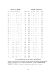
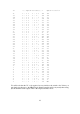
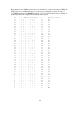
A better solution is to use the switch connections in precisely the order in which they
emerge from the switch PCB. The only effect is to alter the LOCATIONs where we need to
put the "N" codes in the Eprom. The Cobra codes start at 3B for channel 40. Taking the
switch codes in the existing order changes the locations, as shown in the next table.
The effect, of mixing up the binary codes like this, is to change the LOCATIONS from the
HEX number in the
left hand column (which the switch normally supplies to the PLL
inputs) to the HEX number in the right hand column. It is a little tedious to work out all 40
but, once done, does allow you to use ribbon cable instead of individual wires and no links
are needed on the Eprom board.
Once again I must emphasise that we have simply rearranged the LOCATIONS for the "N"
codes in the Eprom. With six connections there can only be 64 different locations and the
channel switch selects 40 of these. Which 40, and in what order is unimportant to the actual
operation of the unit. By mixing up the wires we only alter the selection of which 40
locations out of 64 the switch will select. Regardless of the order of the connections the
result will always be 40 unique location codes out of a possible 64.
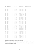
The arrangement of the 8
BITs of the "N" code in each location can also be swapped if it
simplifies the wiring of the Eprom board. The method is, exactly as above, to write each
"N" code in Binary; swap the BITs then convert into HEX to give the code which must be
programmed into Eprom.