
Service manual


19
Eprom Cod
e
s
0 1 2 3 4 5 6 7 8 9 A B C D E F
000
** ** ** ** ** ** ** ** ** ** ** ** ** ** ** F1
001
F2 F3 ** F4 F5 F6 F7 ** F8 F9 FA FB ** FC FD FE
002
FF ** 00 01 02 03 ** 04 05 06 09 07 08 0A 0B 0C
003
0D 0E 0F 10 11 12 13 14 15 16 17 18 ** ** ** **
004
** ** ** ** ** ** ** ** ** ** ** ** ** ** ** **
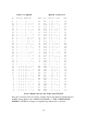
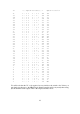
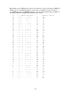
This picture of the codes inside the
Eprom should clarify the situation. We are working
only in HEX now because that is what
Eprom programming units use, so you MUST get
used to it. The
location
is shown by the
left hand column plus the top line. These
numbers are SELECTED by the code from the channel switch itself. We can remove or
disconnect the binary adder ICs
which are no longer required. The content of each location
is the code for that particular channel. Notice, once again, that
some locations are not used
by the switch. These have been marked "**" for clarity but would normally be FF. You
might have noticed that, for this conversion, the code for Channel 15 also happens to be
FF. This is pure coincidence but leads us to the next point.
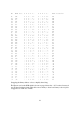
Channel 16 starts at 00 again. Its "N" code ought to be 100 (HEX) or 100000000 (binary)
but, since the Eprom can hold only an eight BIT code, we rely upon the inverting transistor
to supply the "1" to the PLL. Whenever the eighth BIT from the Eprom is "1", therefore,
the ninth BIT of the PLL is "0" from the transistor. The sketch shows how this is achieved.