
Service manual


14
Switch Cod
e
s
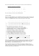
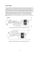
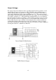
Before you begin a conversion you should ALWAYS use a voltmeter to determine the
switch codes for every channel. Don't rely upon a book to tell you because you'll be
awfully confused if the book is wrong or refers to a different model. Always check. If you
start to design a lot of conversions it will help if you make up a row of
LEDs with
transistors on
stripboard, which you can connect to the PLL input pins. Flicking the
channel switch round causes different
LEDs to light as the code changes and it is an easy
matter to write them down. Keep records of everything you do because it's surprising how
much is forgotten after a couple of months. The switch codes feeding the
Eprom inputs
specify the locations of the output codes. DO remember, however, that the complete
location or "address" comprises the codes from the switch AND any voltage on the
remaining
Eprom inputs. These inputs can be used to switch from one bank of codes to
another in order to change band. Unused inputs should be connected to 0 volts because, if
left floating, they will pick up any stray RF which could be interpreted as a "1". I learnt this
the hard way when
a radio under test actually changed band on transmit. Great for duplex
operation! You can create this effect deliberately
if you need TX downshift for Repeater
operation. Use the rig's own TX line to switch one of the
Eprom inputs thereby swapping
the code bank to one whose codes are programmed for 10 channels lower.