
Service manual


11
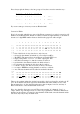
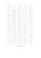
In the foregoing table each bit of the 9 bit code has a value according to its position from
left to right, for instance
:-
256
128 64 32 16 8 4 2 1
1 .
0 1 0
0 . 0 0 0
0 = 140 HEX
or 256+64 = 320 decimal
The left-most bit is called the Most Significant Bit (MSB) and since an
Eprom has only 8
output pins, as mentioned, the MSB must be generated external to the
Eprom. In the table
the range between "a" and "a" obeys a rule that, if either
Eprom output in columns 2 and 3
(or both) is "1", then the MSB must be "0". The simple transistor inverter will perform this
operation.
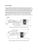
Sometimes you will need to override the operation of the transistor inverter for one band
and it is quite straightforward to hold the transistor base connection permanently high, via a
small value resistor, to keep the MSB low. Another
method which has been used to
"expand" the number of outputs from an
Eprom is to connect a 74LS157 data selector IC to
the
Eprom but a full description of such a device is beyond the scope of this book. At
present, eight outputs should be quite enough for you! By the way
; in some instances you
will not need to use all eight outputs, in which case simply ignore those which you don't
want.
You will find it less confusing if you arrange the internal
Eprom codes such that the unused
output is always "0", although it is not actually necessary, since you will not be connecting
the output to anything. It is worth mentioning, here, that unused
Eprom outputs do not
need to be connected to anything and most certainly should NEVER be connected directly
to either ground or to a supply voltage. Outputs may be connected only to the input pins of
other ICs or to resistors of at least 10k in value. However,
Eprom inputs which are not
used should always be connected to ground, otherwise the ADDRESS of the codes will be
altered and the
Eprom will have to be programmed accordingly.