
Service manual


9
T
r
a
nsistor
I
nv
e
rt
e
r
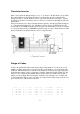
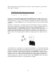
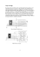
If the codes require the 9th pin always to be a "1" or always a "0" then there is no problem.
We connect that pin to the supply and ignore it. If, however, the state of the pin must
change between "1" and "0" then we do have a problem. The answer is usually to connect
the 8th pin to the base of a transistor whose collector is connected to the ninth pin. The 9th
pin will then
always have the inverse voltage from that which is applied to the 8th pin. When the 8th pin
is "1" the 9th pin will always be "0". (The Export version Cobra 148 GTL DX used this
system with a 15.45 MHz
downmix crystal to begin with. Eventually, however, it occurred
to somebody that by using a 15.00 MHz crystal the range of codes could be shifted to make
pin 9 permanently low and the transistor was no longer needed!)
R
a
ng
e
of Cod
e
s
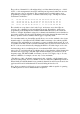
It can be shown that this method can increase the possible number of codes by up to 128
within a particular range, but does not increase the overall number of codes possible with
an
Eprom, which will always be 256 due to the limitation of having only eight output pins.
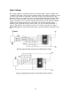
Sometimes the transistor base is connected to both the 7th and the 8th pin. In this way, the
range of codes is shifted a little further and the 9th pin will be low if either the 7th pin or
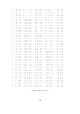
8th pin or both are high. The following list of binary codes will help you to
visualise this
concept. Remember that a total of only 256 codes can be used, but the range can be moved
up or down by use of the transistor inverter.
1 0100 0000 1 0000 1010 0 1101 0100 0 1001 1110 0 0110 1000
•1 0011 1111 1 0000 1001 0 1101 0011 0 1001 1101 0 0110 0111
1 0011 1110 1 0000 1000 0 1101 0010 0 1001 1100 0 0110 0110
1 0011 1101 1 0000 0111 0 1101 0001 0 1001 1011 0 0110 0101
1 0011 1100 1 0000 0110 0 1101 0000 0 1001 1010 0 0110 0100