I
THE CB EPROM DATA BOOK This book is provided, by Lou Franklin and Martin Pickering, for FREE download in Portable Document Format from the following web sites: http://www.cbcity.com http://www.netcentral.co.uk/satcure It may not be sold, copied or distributed for commercial purposes without the consent of the copyright holder, Martin T. Pickering.
CONTENTS INTRODUCTION .............................................................1 SIMPLE As A B C D E F .................................................2 • Mail Boxes - Messages in Code - Select a Channel - Bits in Line • Horrible Hex - Conversion Tables PRACTICAL CONSIDERATIONS ...................................8 • Which Eprom? - Outputs - Transistor Inverter - Range of Codes • Input Voltage - Switch Codes - Output Voltage PRACTICAL EXAMPLES ................................................
Written By: Martin T. Pickering - “The Specialist” © Copyright Martin T. Pickering 1987. All rights reserved. Third Edition 1997. The information in this book is presented for educational purposes only and is not intended as an endorsement of any particular practice. The emphasis is upon using Eproms to convert existing CB transceivers to operate on the Amateur 10 meter band for the use of licensed radio amateurs.
V
INTRODUCTION My interest in CB conversions began some years after Lou Franklin first published his "Screwdriver Expert's Guide" and "The CB PLL Data Book". Consequently I was able to read these and progressed quickly from having a passing interest in CB to actually running a repair business and publishing a quarterly newsletter for like-minded individuals.
Simple as A B C D E F Mail Boxes The Eprom is a basic, mechanical device which can be considered simply as a block of "mail boxes", each holding a message. Each "box" is numbered consecutively. At one end of the block of "boxes" is a slot and by posting the Address or LOCATION NUMBER of a particular "box" into this slot you will make its message contents appear from the output slot at the other end of the block. You can read the contents of ANY "box" in this manner if you know its number.
Messages in Code The actual message in each box consists of just eight numbers, each of which can be "1" or "0". So a typical message might be 1 1 0 1 0 0 0 1 This you will recognise as precisely the same sort of code which a channel switch supplies to a PLL in order to select a channel. The number of each box can also be represented as a code.
All we have to do is to find out what code number comes from the switch for EACH channel and put into each box SELECTED BY THIS NUMBER the NEW code which we want the PLL to see. Putting the codes into the Eprom boxes is called PROGRAMMING and is a simple task which anyone can do, provided, of course, that he has an Eprom Programmer! A Programmer can be bought VERY cheaply and used in conjunction with a personal computer even if you have absolutely no knowledge of computer programming.
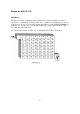
Now, we can convert binary to HEX very easily:8 4 2 1 0 0 0 0 0 0 0 0 1 1 1 1 1 1 1 1 0 0 0 0 1 1 1 1 0 0 0 0 1 1 1 1 0 0 1 1 0 0 1 1 0 0 1 1 0 0 1 1 0 1 0 1 0 1 0 1 0 1 0 1 0 1 0 1 = = = = = = = = = = = = = = = = 0 1 2 3 4 5 6 7 8 9 A B C D E F You seldom need to consider decimal numbers at all. Usually you can go directly from binary to hex. Get used to splitting the binary number into groups of four, with the Least Significant Bit (LSB) on the right hand side.
If we always split the binary codes into groups of four, the conversion remains easy:8 4 2 1 8 4 2 1 8 4 2 1 1 0 0 1 1 1 1 1 0 0 0 0 = 9 F 0 1 1 1 0 1 0 1 0 1 0 0 1 = E A 9 0 0 0 1 0 1 0 1 0 0 1 = A 9 If you can count up to sixteen you can use Hexadecimal! Conversion Tables Now look at a table which shows part of the Eprom contents for a typical conversion. All numbers are in Hexadecimal.
The position of channel 23 is odd and the effect is as if the channel switch goes ---26-2325-24--, so this arrangement in most FCC and European rigs must be taken into account when any new codes are calculated*. This comment applies especially when you are programming a straight sequence of channels without any "hops".
PRACTICAL CONSIDERATIONS Which Eprom? The smallest Eprom currently available is the 2708. This is actually obsolete and has the disadvantage of requiring three different supply voltages: hence, it is never used for new designs. The next larger one is the 2516 or 2716 which, although small, nevertheless has room for 32 banks of 40 channels! It has 11 input pins of which only six would usually be connected to the channel switch.
Transistor Inverter If the codes require the 9th pin always to be a "1" or always a "0" then there is no problem. We connect that pin to the supply and ignore it. If, however, the state of the pin must change between "1" and "0" then we do have a problem. The answer is usually to connect the 8th pin to the base of a transistor whose collector is connected to the ninth pin. The 9th pin will then always have the inverse voltage from that which is applied to the 8th pin.
1 1 1 1 1 1 1 1 1 1 1 1 1 1 1 1 1 1 1 1 1 1 1 1 1 1 1 1 1 1 1 1 1 1 1 1 1 1 1 1 1 1 1 1 1 1 1 1 1 0011 0011 0011 0011 0011 0011 0011 0011 0011 0011 0011 0011 0010 0010 0010 0010 0010 0010 0010 0010 0010 0010 0010 0010 0010 0010 0010 0010 0001 0001 0001 0001 0001 0001 0001 0001 0001 0001 0001 0001 0001 0001 0001 0001 0000 0000 0000 0000 0000 1011 1010 1001 1000 0111 0110 0101 0100 0011 0010 0001 0000 1111 1110 1101 1100 1011 1010 1001 1000 0111 0110 0101 0100 0011 0010 0001 0000 1111 1110 1101 1100 1011 10
In the foregoing table each bit of the 9 bit code has a value according to its position from left to right, for instance:256 128 1 . 0 or 256+64 64 1 = 32 0 16 8 0 . 0 4 0 2 0 1 0 = 140 HEX 320 decimal The left-most bit is called the Most Significant Bit (MSB) and since an Eprom has only 8 output pins, as mentioned, the MSB must be generated external to the Eprom.
Operating Voltage One point which is MOST important is the operating voltage of the Eprom. All those currently available require a supply voltage of 4.75 to 5.25 volts. A zener stabilized supply is essential and I would further recommend the use of a transistor series regulator. The transistor should be rated at 1 Watt minimum, especially for older Eproms whose operating current could exceed 100 milliamps. Alternatively, you could use a regulator device, such as a 7805.
Input Voltage The voltage applied to each input should not exceed the supply voltage or damage will eventually result. If the voltage from the channel switch is more than 5 volts then a couple of resistors are needed on each input to reduce the voltage seen by the Eprom. Some channel switches do not supply a positive voltage but ground the inputs, instead. Where this is true you must connect a resistor between each switch connection and the 5 volt supply to the Eprom.
Switch Codes Before you begin a conversion you should ALWAYS use a voltmeter to determine the switch codes for every channel. Don't rely upon a book to tell you because you'll be awfully confused if the book is wrong or refers to a different model. Always check. If you start to design a lot of conversions it will help if you make up a row of LEDs with transistors on stripboard, which you can connect to the PLL input pins.
Output Voltage The output voltage from an Eprom can be a problem and will often be less than 3.5 volts when the Eprom outputs are connected to a PLL. With PLLs such as PLL02A there is seldom a problem since it usually runs on a supply of no more than 5.5 volts. Since 3.5 volts is more than half the supply voltage the PLL02A sees a "1". The situation with the MC145106P is different since this PLL usually runs with a supply of 9 volts and requires a 6 volt input to guarantee a "1".
Practical Examples The Cobra 148 on 10 meters So much for the theory. Now suppose you want to carry out an actual conversion of a CB radio to the American 10 meter Novice band which covers 28.100 to 28.500 MHz. To make it a little more complicated let's choose the later model of the Export version Cobra 148 GTL DX which uses the PB-010 chassis. A single 15.
So we need to switch in four diodes to add these bits to the appropriate inputs of the binary adders. The end result will be codes of 241 to 241+45 which is 286. In binary this represents Ch40- 1 Ch 1- 0 0 1 0 1 0 1 1 1 1 0 1 0 1 0 0 1 = = 286 = 1 1 E (HEX) 241 = 0 F 1 (HEX) A further complication can be seen here because the Most Significant Bit changes from "0" to "1" somewhere in the range. This means that an inverter transistor must be used as described earlier.
code in Eprom Ch Binary "N"Code 40 39 38 37 36 35 34 33 32 31 30 29 28 27 26 25 24 23 22 21 20 19 18 17 16 15 14 13 12 11 10 9 8 7 6 5 4 3 2 1 1 1 1 1 1 1 1 1 1 1 1 1 1 1 1 1 1 1 1 1 1 1 1 1 1 0 0 0 0 0 0 0 0 0 0 0 0 0 0 0 0 0 0 0 0 0 0 0 0 0 0 0 0 0 0 0 0 0 0 0 0 0 0 0 0 1 1 1 1 1 1 1 1 1 1 1 1 1 1 1 0 0 0 0 0 0 0 0 0 0 0 0 0 0 0 0 0 0 0 0 0 0 0 0 0 1 1 1 1 1 1 1 1 1 1 1 1 1 1 1 0 0 0 0 0 0 0 0 0 0 0 0 0 0 0 0 0 0 0 0 0 0 0 0 0 1 1 1 1 1 1 1 1 1 1 1 1 1 1 1 1 1 1 1 1 1 1 1 1 0 0 0 0 0 0 0 0 0 0 0 0
Eprom Codes 000 001 002 003 004 0 ** F2 FF 0D ** 1 ** F3 ** 0E ** 2 ** ** 00 0F ** 3 ** F4 01 10 ** 4 ** F5 02 11 ** 5 ** F6 03 12 ** 6 ** F7 ** 13 ** 7 ** ** 04 14 ** 8 ** F8 05 15 ** 9 ** F9 06 16 ** A ** FA 09 17 ** B ** FB 07 18 ** C ** ** 08 ** ** D ** FC 0A ** ** E ** FD 0B ** ** F F1 FE 0C ** ** This picture of the codes inside the Eprom should clarify the situation. We are working only in HEX now because that is what Eprom programming units use, so you MUST get used to it.
Channel Switch Codes The codes from the channel switch don't matter, as mentioned previously, since they serve only to SELECT the LOCATION in Eprom for the actual "N" code we need. Consequently, we can often make the hardware connections simpler, although the encoding of the Eprom might become more complex. The Export Cobra is a good example because the channel switch wires, as they come off the switch PCB, are in the order P5 P2 P4 P1 P3 P0 starting at the side near to the chassis.
Ch Old Loc.
The MB8719 used in Uniden Chassis This PLL is unusual in having only seven programming pins but an internal inverter which makes it work as if it had eight. The seventh pin controls the MSB which is always "1" (~64) or "0" (.128). Unfortunately, this system means that the range of codes is limited, going from 64 minimum to 128+63 = 191 maximum: a range of 127 channels or just three banks of 40, in practice. The early export Cobra 148GTL DX uses three crystals with this PLL.
ch <...Eprom Contents...
Rigs which use an 11 MHz crystal can not be modified so easily as the range of MB8719 divide ratios is not sufficiently large. It is necessary to change the crystal. A value of 11.755MHz produces 28.105MHz when the "N" code is 64 and leaves the possibility of producing another two higher bands with the same crystal. ch 40 39 38 37 36 35 34 33 32 31 30 29 28 27 26 25 24 23 22 21 20 19 18 17 16 15 14 13 12 11 10 9 8 7 6 5 4 3 2 1 <....Eprom Contents....
If, however, a conversion board can be fitted which uses the MC145106P IC then the range of "N" codes is greatly extended and permits the standard crystal of either 11.1125 or 11.3258 MHz to be retained without the need to buy a specially made crystal. The conversion board uses an Eprom to translate the switch codes into "N" codes for the new PLL IC and the full range of frequencies from 28.105 to 29.695 MHz can be achieved, together with 100 kHz repeater downshift on transmit.
LOC. EPROM CONTENTS FOR 11.1125 CRYSTAL 0000 0008 0010 0018 0020 0028 0030 0038 0040 0048 0050 0058 0060 0068 0070 0078 0080 0088 0090 0098 00A0 00A8 00B0 00B8 OOCO 00C8 00D0 00D8 00E0 00E8 00F0 00F8 0100 0108 0110 0118 0120 0128 0130 0138 0140 0148 .. .. 02 80 87 45 C5 25 .. .. A2 60 67 E5 15 95 .. .. 52 D0 D7 35 B5 75 .. .. .. .. .. .. .. .. .. .. F2 08 OF 8D 4D CD .. .. .. .. 03 81 .. 46 C6 26 .. .. A3 61 .. E6 16 96 .. .. 53 D1 .. 36 B6 76 .. .. .. .. .. .. .. .. .. .. F3 09 .. 8E 4E CE .. .. .. .. .
LOC. EPROM CONTENTS FOR 11.3258 CRYSTAL 0000 0008 0010 0018 0020 0028 0030 0038 0040 0048 0050 0058 0060 0068 0D70 0078 0080 0088 0090 0098 00A0 00A8 00B0 00B8 00C0 00C8 00D0 00D8 00E0 00E8 00F0 00F8 0100 0108 0110 0118 0120 0128 0130 0138 0140 0148 .. .. 1A 98 9F 5D DD 3D .. .. BA 78 7F FD 05 85 .. .. 42 C0 C7 25 A5 65 .. .. .. .. .. .. .. .. .. .. E2 10 17 95 55 D5 .. .. .. .. 1B 99 .. 5E DE 3E .. .. BB 79 .. FE 06 86 .. .. 43 C1 .. 26 A6 66 .. .. .. .. .. .. .. .. .. .. E3 11 .. 96 56 D6 .. .. .. .. .
28
Another Eprom Board The previous design was specifically for certain rigs but this Eprom board for the Cobra may be used with most versions. Six pull-up resistors are connected to the channel switch inputs O to 5, which are arranged exactly in the right order for the ribbon cable from the channel switch itself. Eprom inputs A6 to A10 are available to select several more bands, if required. However, no more than 5 volts must be applied to these inputs unless series resistors (e.g. 10k for +9v) are connected.
Example The TC9109 and MB8733 PLL ICs are both similar in that they use eight of the connections between the channel switch and the LED channel number display as inputs to determine the "N" code. In effect, there is a built-in "Prom" which translates the LED code into the "N" code and the PLL can not, therefore, be fooled. They produce the 40 FCC approved channels, but no others. Unlike most PLLs, these produce the transmit frequency by doubling the VCO output, instead of by mixing.
TC9109 input codes. LC7137 input codes.
µPD858 – Example There is a range of AM/SSB rigs which includes the Cobra 138/139 XLR, Realistic TTRC457/458/449 and "President Adams" that use the uPD858 PLL and can readily be converted to the American "Novice" Band. This particular PLL uses BCD coding and the standard "N" code values are 91 to 135. Although ten pins exist on this PLL, only eight are fed by the channel switch. The codes on pins 22 and 19 do not change and are permanently grounded.
Adams uPD858 "Novice" conversion pins-22 ch.
34
35
µPD2824 – Example The uPD2824 is a popular PLL in America but is internally programmed for only forty channels. The internal "N" codes are 91 to 135 with the usual "hops". Notice that these are exactly the same "N" codes which were used in the uPD858 rigs but they are accessed, here, by a channel switch which provides a BCD output of 00 to 39. This is one of the "impossible" chips and must be replaced if we are to use the rig on the 10 meter band.
Cobra 146 GTL uPD2824 "Novice" using MC145106P FCC channels dec.
38
39
PLL02A Example The PLL02A chip is used extensively for export models and in 40 channel rigs in the USA. It is a versatile PLL with nine programming pins, however the export rigs do not take advantage of this and normally switch in different crystals to change the frequency band. The crystal fitted for the FCC band is normally 10.0525 MHz followed by a doubler circuit, although a few export models use a crystal of twice this frequency at 20.105 MHz without the doubler.
Ham International "Novice" conversion "N" code PLL02A pin numbers Eprom contents location ch dec.
A General Purpose Eprom Board We have designed a simple printed circuit board which you could use for experimentation, or even build and sell to your friends. It allows you to fit a 2516, 2716, 2532, 2764, 27128 or 27256 Eprom and the layout makes provision for all the resistors you are likely to need. The design includes a lot of options which you may not require and it is left to you to decide which components you want to fit for your particular conversion, based on the information given in this book.
43
APPENDIX 1 Erasing Eproms, by definition, are erasable under Ultra Violet light. Since many second hand Eproms are available, cheaply, it is worth considering the use of such devices to save money. Before you can utilize them you must erase the existing contents, effectively resetting all bytes to FF. The "window" in each device is not glass but quartz which allows UV light to pass through much more readily than glass does. The UV light must be within a specific frequency band to be effective.
Non-E-proms There are also some plastic encapsulated "Eproms" which can't be erased. These are known as One Time Programmable (OTP) Eproms and can be somewhat cheaper than the standard type, since you don't pay for a ceramic housing with a quartz window. Obviously, it's no use buying these second hand! The programming time for these can be seconds, rather than minutes. They are ideal for high volume production, but of little use to the experimenter.
Programming Many designs for Eprom programming units have been published. Some are very good, some mediocre. All work well, within their limitations. All the units, commercial or home built, which connect to a PC are very versatile because you have the full programming power of the PC to assist. Usually you can type the HEX codes directly into the computer memory, then "dump" them into the Eprom. It is also possible to save the relevant section of memory to disc or tape.
Gang Bangers If you are going into Eprom copying in a big way there are commercial units (known as "gang bangers" in the trade) which will program several Eproms at a time. The simpler type for connection to a PC will seldom program more than one device at a time, but is far more versatile for development purposes. Manual Programming It is actually possible to enter data into an Eprom without using an automatic programming unit at all.
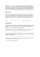
In the VERY crude circuit shown here you must first set the binary location code on switches A0 to A10. Then set the binary data on switches D0 to D7. Close S1; poke the “PROG” button for an instant (can you guess 50mS ?); open S1. It might work! For a typical 2716, the following conditions must exist during programming mode: Vcc must be at +5v; Vpp must be at +26v; Program (PGM) at 0v; the required contents present on the output pins and the location code on the input pins.
Eproms The 2716 and 2516 have 24 pins and are generally interchangeable, although slight differences in programming parameters exist between the various manufacturers' devices. The 2732 and 2532 also have 24 pins and have the same capacity as each other but BEWARE: they are NOT pin for pin compatible, as the sketches at the back of this book show! The 2764 and 27128 have 28 pins and can be interchanged, but bear in mind that the 27128 has twice the capacity of the 2764.
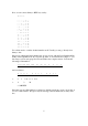
Decimal to Binary The following simple computer program in BASIC will convert any decimal number less than 4096 into Binary.
APPENDIX 2 Pin Out Sketches 51
...more pinouts...
APPENDIX 3 (not included in the original publication) Convert to 10 metres the Chip Way You may wonder why an ordinary mortal who is not a licensed Amateur should have wished to design a ten metre conversion which he can't legally use. The simple answer was, of course, money and the design was a natural development from much work on other successful conversions for C.B. Radios.
Now, the original idea was to use a simple transistor mixer to combine the V.C.O. output with the output from IC2. The difference frequency would then be filtered out by an L-C 'tank' circuit to be passed to the LC7137. This idea failed to work in practice and was abandoned in favour of the digital approach (Ref. 1) pioneered by Bill Sparks G8FBX and Colin Horrabin G3SBI. Instead of mixing and filtering, we simply blank out a certain number of Hz from the V.C.O. output during each second.
55
By this method we blank out one V.C.O. pulse after the input square wave goes low, reset the square wave at the end of the blanked V.C.O. pulse, then do nothing until the square wave input goes low again. Since the circuit entirely eliminates the need for any timing elements, but relies totally on pulse falling edges, its operation is independent of the frequencies involved and noods no adjustment.
Normally IC2 would be linked directly to IC4 but, if IC3 is added, there is an option to lower the frequency band by the use of an extra divider stage. I leave it to you to calculate the actual frequencies which would be achieved. Note that it might be necessary to adjust the values of C6 and C7 if this option is used.
2) "How to Convert 'Unconvertible' CB rigs to Work on the Ten-Metre Band". Hugh Allison. "The Short Wave Magazine" March 1984. 3) "The CB PLL Data Book". Lou Franklin. ISBN 0-943132-05-3. 4) "The CB Eprom Data Book". Martin Pickering. ISBN 0-943132-16-9 5) "The Midnight Express" CB Radio repair manual. Martin Pickering. Shopping List Resistors 5% 0.4W carbon film 100Ω .............R13 560Ω .............R12 1kΩ...............R2, R4, R8, R9, R16, R17 4k7Ω .............R11 10kΩ .............
• “A” channel A frequency between legally allocated CB channels which may not be used for CB transmissions. • Erasing Changing every single Bit inside an Eprom to "1". That is the same as changing every Byte to 11111111 or FF HEX. • Actinic Radiating light which can chemical change. • FET “Field Effect Transistor” A transistor which changes its internal resistance with the voltage applied to its “gate” connection.
• OTP “One Time Programmable” A type of (E)prom which can not be erased. • VCO "Voltage Controlled Oscillator" • Vpp The IC pin which must be connected to a specified voltage in order to allow programrning of the device. • P.C. “Personal Computer” • PD “Phase Detector” This PLL pin provides a pulsed output whose average voltage, after filtering and smoothing, controls the frequency of the VCO.