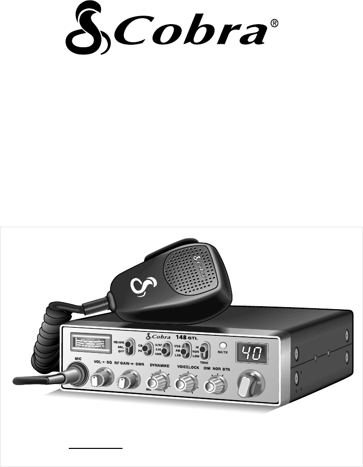
OPERATING INSTRUCTIONS FOR YOUR 40 CHANNEL CITIZENS BAND SSB/AM 2-WAY MOBILE RADIO Model 148 GTL Nothing comes close to a Cobra™ PRINTED IN CHINA ©2002 COBRA ELECTRONICS CORPORATION 6500 WEST CORTLAND STREET CHICAGO, IL 60707 USA 480-046-P
How To Use Your Serial No. Date of Purchase Dealer Name Keep this manual for detailed information about your Cobra CB Radio System. SAVE YOUR SALES RECEIPT, THE CARTON AND “PACKING” FOR POSSIBLE FUTURE USE. 40-CHANNEL, CITIZENS BAND SSB/AM 2-WAY MOBILE RADIO Model 148 GTL Contents Page Section I: Introduction ..........................................................................................2 Section II: Specifications ...............................................................................
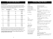
Section I Introduction Section II Specifications FREQUENCY RANGE The COBRA 148GTL transceiver represents one of the most advanced SSB/AM two-way radios ever designed for use as a Class D station in the Citizens Radio Service. This unit features advanced Phase Lock Loop (PLL) circuitry, which is used in the AM mode and in the upper and lower single sideband modes, providing complete coverage of all 40 channels shown below.
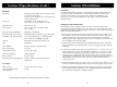
Section II Specifications (Cont.) Section III Installation LOCATION RECEIVER Sensitivity SSB: 0.25 µV for 10dB (S+N)/N at greater than 1/2-watt of audio output. AM: 0.5 µV for 10 dB (S+N)/ at greater than 1/2watt of audio output. Selectivity AM: 6dB @ 3 KHz, 50 dB @ 9 KHz. SSB: 6 dB @ 1.1 KHz, 60 dB @ 2.3 KHz. Image Rejection More than 65 dB. IF Frequency AM: 7.8 MHz 1st IF, 455 KHz 2nd IF. SSB: 7.8 MHz. Adjacent-Channel Rejection 60 dB AM & 70 dB SSB.
Section III Installation (Continued) Section III Installation (Continued) IGNITION NOISE INTERFERENCE TUNING THE ANTENNA FOR OPTIMUM SWR Use of a mobile receiver at low signal levels is normally limited by the presence of electrical noise. The primary source of noise in automobile installations is from the generator and ignition system in the vehicle. Under most operating conditions, when signal level is adequate, the background noise does not present a serious problem.
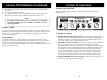
Section III Installation (Continued) D. Try a different location on your car (keeping in mind the radiation pattern you wish). E. Is the antenna perfectly vertical? F. Try a different location in your neighborhood. Stay away from large metal objects when adjusting (metal telephone or light posts, fences, etc.). Section IV Operation CONTROLS AND INDICATORS There are thirteen controls and three indicators on the front panel of your COBRA 148GTL.
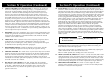
Section IV Operation (Continued) Section IV Operation (Continued) 4. SWR CAL CONTROL (outer dual concentric). In order for you to achieve maximum radiated power and the longest range, it is important that your antenna be in good condition, properly adjusted and matched to your transceiver. The Built-in SWR (standing wave ratio) meter lets you easily measure your antenna condition. To operate this function, connect your antenna to the transceiver antenna output connector.
Section IV Operation (Continued) Section IV Operation (Continued) B. INDICATOR FUNCTIONS 7. Set the CHANNEL selector switch to the desired channel. 1. S-METER. Swings proportionally to the strength of the incoming signal. 8. Adjust the VOICE LOCK control to clarify the SSB signals or to optimize AM signals. 2. RF METER. Swings proportionally to the RF output power. 3. SWR METER. Swings proportionally to the ratio of standing wave voltage and RF output.
Section IV Operation (Continued) pitched whistle or a high-pitched whistle) you will hear the increase in the output tone of the receiver. If the incorrect mode is selected, an increase in tone of a whistle applied to the transmitter will cause a decrease in the resultant tone from the receiver.
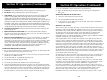
Section IV Operation (Continued) Section IV Operation (Continued) 3 Fig. 2. Microphone Cable Preparation. To wire the microphone cable to the plug provided, proceed as follows: 3 4 2 1 2 4 1 Fig. 4. Microphone plug pin numbers viewed from rear of pin receptacle. Be sure that the housing and the knurled ring of Fig. 3 are pushed back onto the microphone cable before starting to solder.
Section V Maintenance and Adjustment The COBRA 148GTL transceiver is specifically designed for the environment encountered in mobile installations. The use of all solid state circuitry and its light weight result in high reliability. Should a failure occur, however, replace parts only with identical parts. Do not substitute. Refer to the schematic diagram and parts list.
Section VI Appendix (Continued) Section VI Appendix (Continued) A FEW RULES THAT SHOULD BE OBEYED 1. You are not allowed to carry on a conversation with another station for more than five minutes at a time without taking a one-minute break, to give others a chance to use the channel. 2. You are not allowed to blast others off the air by over-powering them with illegally amplified transmitter power, or illegally high antennas.
INSTRUCCIONES DE USO DEL 40 CANALES RADIO BIDIRECCIONAL MÓVIL SSB/AM DE BANDA CIUDADANA Modelo 148 GTL Nada se compara a Cobra™ IMPRESO EN CHINA ©2002 COBRA ELECTRONICS CORPORATION 6500 WEST CORTLAND STREET CHICAGO, IL 60707 USA 480-046-P
Instrucciones de uso del Número de serie Fecha de compra Nombre del distribuidor Conserve este manual como referencia detallada de su sistema de radio CB Cobra. GUARDE EL COMPROBANTE DE VENTA, LA CAJA Y LOS MATERIALES DE EMBALAJE, YA QUE POSIBLEMENTE TENGA QUE UTILIZARLOS EN EL FUTURO. RADIO BIDIRECCIONAL MÓVIL SSB/AM DE 40 CANALES DE BANDA CIUDADANA Modelo 148 GTL Índice Página Sección I: Introducción ................................................................................................
Sección I Introducción Sección II Especificaciones INTERVALO DE FRECUENCIAS GENERALES El transmisor-receptor COBRA 148GTL es uno de los radios transmisores-receptores SSB/AM más avanzados que se han diseñado para usarse como estación de clase D en el servicio de radio ciudadana.
Sección II Especificaciones (cont.
Sección III Instalación (continuación) INTERFERENCIA POR RUIDO DEL ENCENDIDO El uso de un receptor móvil con señales de baja intensidad por lo general es limitado por la presencia de ruido eléctrico. Al instalar la unidad en un automóvil, las principales fuentes de ruido son el generador y el sistema de encendido del vehículo. En la mayoría de las condiciones operativas, el nivel de intensidad de la señal es adecuado y el ruido de fondo no representa problemas graves.
Sección III Instalación (continuación) D. Coloque la antena en otro lugar del vehículo (tenga en cuenta el patrón de radiación que desea). E. ¿Está la antena perfectamente vertical? F. Pruebe en otro lugar de su vecindario. Manténgase lejos de objetos metálicos grandes (postes metálicos de teléfono o electricidad, cercas, etc.). Sección IV Operación CONTROLES E INDICADORES En el panel delantero del radio COBRA 148GTL hay 13 controles y tres indicadores.
Sección IV Operación (continuación) Sección IV Operación (continuación) 4. CONTROL DE CALIBRACIÓN DE RELACIÓN DE ONDA ESTACIONARIA (SWR CAL CONTROL) (parte exterior del control doble concéntrico). Para que usted obtenga la máxima potencia radiada y el mayor alcance, es importante que la antena esté en buen estado, bien ajustada y que corresponda al transmisorreceptor. El medido integrado de relación de onda estacionaria (SWR) le permite medir fácilmente el estado de la antena.
Sección IV Operación (continuación) B. FUNCIONES DE LOS INDICADORES 1. MEDIDOR DE INTENSIDAD DE SEÑAL. Se mueve proporcionalmente a la intensidad de la señal recibida. 2. MEDIDOR DE RADIOFRECUENCIA (RF). Se mueve proporcionalmente a la potencia de salida de radiofrecuencia. 3. MEDIDOR DE RELACIÓN DE ONDA ESTACIONARIA (SWR). Se mueve proporcionalmente a la relación entre el voltaje de la onda estacionaria y la salida de radiofrecuencia.
Sección IV Operación (continuación) Si se escucha una señal de banda lateral inferior (LSB) cuando el receptor está en la modalidad USB, la señal no será inteligible, no obstante cuántos ajustes se hagan a la sintonización. Es más fácil comprender por qué sucede esto si considera que al aplicar la modulación al micrófono del transmisor en la modalidad USB se incrementa la frecuencia de salida del transmisor, mientras que la frecuencia de salida del transmisor se reduce en la modalidad LSB.
Sección IV Operación (continuación) Sección IV Operación (continuación) 3 Figura 2. Preparación del cable del micrófono. 2 4 1 Para conectar el cable del micrófono a la clavija provista, siga estos pasos: 3 4 2 1 Figura 4. Números de pata de la clavija del micrófono, visto desde la parte trasero del receptáculo de las patas. Compruebe que la estructura y el anillo de la figura 3 estén hacia atrás, sobre el cable del micrófono, antes de comenzar a soldar.
Sección V Mantenimiento y ajustes El transmisor-receptor COBRA 148GTL ha sido diseñado de manera específica para el entorno que usualmente está presente en instalaciones móviles. El radio únicamente tiene circuitos de estado sólido y es una unidad ligera de alta fiabilidad. Sin embargo, si llegase a ocurrir una avería, únicamente debe reemplazar las piezas por otras idénticas. No utilice otras piezas de repuesto. Consulte el diagrama esquemático y la lista de piezas.
Sección VI Apéndice (continuación) Sección VI Apéndice (continuación) REGLAS QUE DEBE OBEDECER UTILICE EL CANAL 9 ÚNICAMENTE PARA MENSAJES DE EMERGENCIA 1. Las conversaciones con otras estaciones no deben durar más de cinco minutos sin que haya una pausa de un minuto o más para permitir que otras personas utilicen el canal. La Comisión Federal de Comunicaciones de Estados Unidos (FCC) ofrece los siguientes ejemplos de los tipos de comunicación permitidos y prohibidos en el canal 9.