
User`s manual

100-M0074X1 8 of 24
www.cobham.com/gms
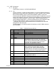
19 USB Gnd
20-30 Not connected
31 RS232 Control Tx
32 RS232 Control-Rx
33 RS232 GND
34-36 Not connected
37 Audio right + Not applicable for MDT-A
38 Audio right - Not applicable for MDT-A
39
Audio right line opt. Pin 39 is connected to pin 38 for audio right channel
input impedance of 600 ohms , balance in (mic or line
level). Not
applicable for MDT-A
40 Audio right GND Not applicable for MDT-A
41 Audio left + Not applicable for MDT-A
42 Audio left - Not applicable for MDT-A
43 Audio left line opt Pin 43 is connected to pin 42 for audio left channel
input impedance of 600 ohms; balance in (mic or line
level). Not
Applicable for MDT-A.
44 Audio left GND Not applicable for MDT-A
For the MDT-A the I/O connector is limited to only power, ground, USB connections and
RS232 functions. Analog video input functions are not provided.
4.1.1.3 ASI BNC Input Connector
The BNC connector is provided for accepting ASI (Asynchronous Serial Interface) data.
The MDT-A can accept the ASI only data streams.
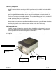
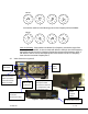
4.1.2 Frequency Select Switches
There are four external rotary switches mounted into the chassis of the MDT-A (see
Figure 1 & 2). They are used to control RF frequency selection manually. Frequency
selection can also be controlled through GMS control software; see section 6. The rotary
switches can be disable or enable using GMS control software; refer to section 6.3.3.2
under Configuration/Special Setup/Others. The most significant switch (SW100)
represents 1000 MHz (0-9) units, the second switch (SW101) represents 100 MHz (0-9)
units, the third switch (SW102) represents 10 MHz (0-9) units and the fourth switch
(SW103) represents 1 MHz (0-9) units. Hence the highest switch selection can be
9999MHz and the lowest is 0000 MHz.
For example with the switches in the following positions, the frequency will read 2014
MHz: