
User`s manual

100-M0074X1 6 of 24
www.cobham.com/gms
3.0 Theory of Operation
The MDT-A accepts DVB ASI according to MPEG-2 specifications (Video MPEG-2 and Audio MPEG-1
layer II).
The TS stream is then sent through a DVB-T compliant FEC encoder and C-OFDM modulator. This is
output from the FPGA based modulator core as digital I/Q signals that are converted to Analog I/Q
signals and applied to an I/Q Modulator. The LO that provides the carrier to this I/Q modulator comes
from a low phase-noise programmable synthesizer. The modulated RF output of the I/Q modulator IC
is sent through amplifier chain and ultimately output to the outside world. Programmable attenuators
in the RF processing chain provide signal leveling.
The transmitter is microprocessor controlled. Normally the transmitter is controlled either through an
RS-232 or USB interface via either GMS’ MS Windows control SW or a simple command line interface.
Local Frequency control is also available via rotary switches on the side of the housing.
4.0 Hardware Overview
The MDT-A accepts ASI only data streams. In addition, the MDT-A can be mounted in an inline
professional camera unit (this is an optional enclosure for mounting the MDT-A for professional
camera applications). The hardware configuration is shown below:
4.1 MDT-A
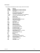
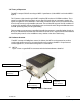
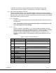
Figure 2 shows a typical MDT-A transmitter with the hardware elements identified.
Figure 2 – MDT-A Connectors
“ASI Input” (BNC
Connector)
DB
-
44 Connector
(I/O and Power)
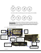
Frequency
Select Switches.
“RF OUT” SMA Connector)
SW100