
User`s manual

100-M0074X1 21 of 24
www.cobham.com/gms
transmitter frequency (MDT-A) is set for 2000MHz, then the MDR can be set for 2000 MHz (it
automatically calculates the IF frequency based on pre-programmed LO information of the down-
converter). The IF frequency changes as the RF frequency changes; the LO remains constant.
On non-GMS commercial digital receiver it may be necessary to program the receiver with the IF
frequency directly. The user may need to do the simple math to arrive at the IF frequency so that it
can be entered into the receiver. The down-converter LO must be known. The math involve is
as follows: “ RF (transmitter frequency) – LO (local oscillator) = IF frequency”. For example, it the
transmitter is set for 2000MHz and the LO of the down-converter is 2800MHz then the IF
frequency is -800MHz (2000-2800MHz = -800). The receiver will need to be set to 800MHz to
receive the transmitter frequency of 2000MHz. Each time the transmitter frequency is changed the
IF must be re-calculated and entered into the receiver. It must also be mentioned, as you may have
noticed, a negative LO may indicate the receiver wants the signal to be inverted. See section 5.3.3.2
for inverting the signal.
8.2 Local and Remote Power
Customers may have the option of using remote or local power to power up a down converter
depending on the receiver used. GMS’ MDRs (Messenger Digital Receiver) and MSRs (Messenger Smart
Receiver) can provide DC +12 volts to power the D/C remotely through the RF cables. Refer to GMS’
MDRs or MSRs operating instructions for turning on the DC power for the D/C when using remote
power.
If the D/C is located relatively close to the receiver then using remote power makes sense. However, if
the D/C is located at great distances away from the receiver there may be excessive DC voltage drop in
the coax cable (due to cable resistances). If this is the case then local DC power should be considered
as discussed below. If unsure of the DC voltage drop measure the DC voltage present (using a DMM) at
the end of the coax cable run. The D/C normal operating voltage is approximately +12Vdc but can
operate down to +10Vdc.
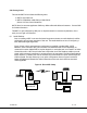
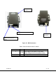
• Local power is provided by applying +12Vdc to pin 1, GND to pin 3 of the DB-9 connector located on
the bottom of the D/C. The +12 Volt power supply must be able to source at least 500mA. The power
switch (located on the side of the D/C) enables the user to control the ‘ON’/’OFF’ positions for local
power. If using local power then ensure the remote power (if the receivers have this capability) is
turned off.