
User`s manual

100-M0074X1 19 of 24
www.cobham.com/gms
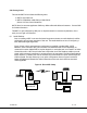
1. Install omni-directional antennas onto the MDT-A RF output port and Down- Converter (D/C)
RF input port. Note: Transmitters should not be powered on without a load. Doing so
could cause the output PA to stop working. A proper heat sink is also required.
2. Attach the breakout cable (DB-44 end) to the MDT-A unit (if unit is mounted in an Inline
Camera Mount Box this step does not apply).
3. Attach a RF cable from the D/C IF output port to RF in port of the receiver.
4. Attach an ASI source to MDT-A BNC ASI input . If unit is mounted in an Inline Camera Mount
Box then attach ASI to appropriate BNC ASI input connector
5. Attach a video cable from one of the BNC video output ports on the receiver to a video
monitor.
6. To prepare to power the MDT-A unit, attach the red and black wires from the breakout cable to
+12V terminal and ground of power supply, respectively (if unit is mounted in an Inline Camera
Mount box then attach +12 Volt battery). NOTE: The power supply (for the transmitter) needs
to be able to provide at least 1.5 Amps of current at a nominal +12VDC input. If using a
commercial DVB-T receiver follow the manufacturer’s instructions for powering the unit.
7. Turn on the ASI source and video monitor equipment.
8. Apply power to the MDT-A and the receiver unit (Inline Camera Mount boxes have power
switches which must be turned on). Also ensure the down converter is powered (+12 Vdc to
pin 1, GND to pin 3 of the DB-9 pin connector located on the bottom side of the D/C). If the
down converter is installed in a camera mount box it will have a power switch on the side of
the unit. Ensure the switch is turned to the “On” position.
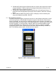
9. After approximately 10 seconds, the link should be established and video provided by the
source should be displayed on the monitor.
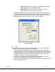
The initial checkout described above is simply to check the basic video operation of the MDT-A
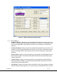
unit. For further details on monitoring and controlling the MDT-A using GMS’ optional MS
Windows-based MDT-A Configurator software program, see Section 6.0.
7.0 Specifications
The following sections outline the overall specifications for the MDT-A unit.
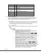
7.1 Transport Stream
Standard: per ISO/IEC 13818-1
Packet Size: 188 byte
ASI Input :Allows MPEG2 transport stream per EN 300 744
Bit Rate: 100Kps – 30Mbps
7.2 RS-232 Interfaces/RCU/USB
Control Port: 3-wire interface (Tx,Rx,Gnd)
USB 1.0
RCU A remote portable control unit is also available
In addition a “Data” RS232 channel under development will be dedicated for low-rate data
to be transmitted along with the audio and video.
7.3 COFDM RF Output
Output Frequency: 0.36 to 6 GHz (In-Bands).
Frequency step size is 500 KHz for all bands except S2 (1999-2500 MHz) which is 250 KHz.
Bandwidth: Selectable 6, 7 or 8 MHz