
User`s manual

100-M0074X1 14 of 24
www.cobham.com/gms
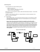
to verify that a write operation has been correctly performed. An example scenario would be
to 1) enable all fields, 2) change desired field(s), 3) perform a ‘Update’ (write) operation, 4)
perform a ‘CLR’ operation and 5) perform a ‘Query’ operation. As a result of the ‘Query’
operation, the fields on the screen should all update to those values that were written during
the ‘Update’ operation.
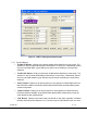
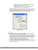
• “Store All Setup Pages” Button: Clicking on this button will store all setup pages, even if
they are not shown.
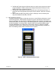
• “Reset Tx” Button: Clicking on this button will reset/reboot the MDT-A unit. The system
parameters will be restored to the last saved settings. Reset time is approximately 20 seconds.
5.3.2 Field Definitions
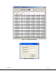
There are several different fields that can be configured by the MDT Configurator. The fields
located in the main screen of Figure 5 and their associated values are defined in Table 3 below.
Also noted in the table is whether the field is read, write-able or both
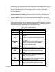
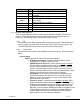
Table 3 – MDT-A Field Definitions
Field R/W Description
Unit Name
R/W
Allows the user to assign a unique unit name to the
MDT.
Unit Number
R/W
Allows the user to assign a unique unit number to
the MDT
RF Freq
(MHz)
R/W
RF output frequency. Desired frequency is entered
in MHz (i.e., 1.296 GHz would be entered as 1296).
Default frequency step size is 500 KHz. For S2 band
it’s 250 KHz.
Modulation
Mode
R/W
Modulation mode. Desired modulation mode is
selected from the following values: C-OFDM
(default) Off (shuts off modulation) or I/Q CAL ON
(puts unit in calibration mode).
C-OFDM
Bandwidth
R/W
COFDM transmit bandwidth. Desired bandwidth is
selected from the following values: 6, 7 or 8 MHz.
C-OFDM
Mode
R/W
COFDM modulation type. Desired COFDM
modulation type is selected from the following
values: QPSK, 16QAM or 64 QAM (only in ASI
mode)
Mod Guard
Interval
R/W
Modulation guard interval size. Desired modulation
guard interval size is selected from the following
values: 1/32, 1/16, 1/8 or ¼.
Modulation
FEC
R/W
Modulation FEC (Forward Error Correction) rate.
Desired modulation FEC rate is selected from the
following values: ½, 2/3, ¾, 5/6, 7/8 .
Channel Rate
(Mbps)
R
Channel rate is displayed based on parameters
selected such as COFDM mode, FEC and Guard
Interval. Channel rate must be set to be greater
than the ASI stream rate. Set the channel rate to at