
User`s manual

100-M0074X1 11 of 24
www.cobham.com/gms
4.2.1.3 Video Input (Not applicable to MDT-A)
The MDT in-line camera enclosure uses female BNC connectors for video input.
Component, Composite or S-Video input is accepted (see section 6 for setting video
input type). J3 BNC connector marked “Y/COMP” is a dual use input connector; a)
Composite Video or b) Luminance when used with Component video. J2 BNC connector
marked “C/Pr” is a dual use input connector; a) Chroma when used with S-Video or b) Pr,
the red component minus the luminance information used with Component Video. J8
BNC connector marked “Pb” is the blue component minus the luminance information
used with Component Video. These video inputs are applicable to the SDMT-C and
MDT-3 units.
4.2.1.4 Power Switch
An LED indicator rocker switch is provided for controlling power to the unit.
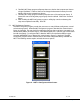
4.2.1.5 LCD Display
An optional LCD display with a front control panel is available for the inline camera
mount unit. Many of the control functions which are normally handled through the
software interface and a PC can now be accessed directly with the front control panel
and displayed on the LCD such as changing frequencies, checking video lock status
among many others.
4.2.1.6 SDI/ASI Input
A BNC connector is provided for Asynchronous Digital Interface (ASI) input data
streams.
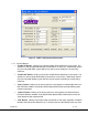
5.0 Software Overview
Configuration, control and monitoring of the MDT-A unit is accomplished by using GMS’ optional (sold
separately) MS Windows-based MDT Configurator software program. This Graphical User Interface
(GUI) program provides the end user with a straightforward way to interface with the MDT-A. During
normal operation, once a MDL link is established, the MDT Configurator GUI does not need to be
active and can be disconnected from the MDT-A.
5.1 System Requirements
The MDT Configurator program has been developed and tested on Windows 2000, Windows XP
and Windows NT. Although the MDT Configurator program may work properly on other operating
systems, only the Windows 2000, Windows XP and Windows NT environments have been used at
GMS and no support or assistance can be provided concerning other operating systems.
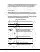
5.2 Installation
The following instructions outline the installation process for the MDT-A Configurator program:
1. Insert provided CD-ROM into computer.
2. Click on ‘setup.exe’ file. This will launch the GMS_MDT Configurator Setup program and
several initial setup files will begin to be copied onto the computer.
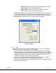
3. After the initial setup files are copied over, the GMS_MDT Configurator Setup program will
prompt the user to close any applications that are running. Once all other programs are
exited, click on the ‘OK’ button.