User’s Manual The most important thing we build is trust. Messenger Digital Transmitter – ASI Version MDT-A 100-M0074X1 05/28/09 Cobham Surveillance GMS Products 1916 Palomar Oaks Way Ste 100 Carlsbad, CA 92008 T: 760-496-0055 F: 760-496-0057 www.cobham.
Table of Contents 1.0 ACRONYMS................................................................................................................................................................... 4 2.0 INTRODUCTION......................................................................................................................................................... 5 2.1 Key System Features ........................................................................................................................
List of Tables Table 1 - I/O DB-44 Connector Pin Out......................................................................................................................... 7 Table 2 - I/O DB-15 Connector Pin Out.......................................................................................................................10 Table 3 – MDT-A Field Definitions ................................................................................................................................
1.0 Acronyms This section lists and describes the various acronyms used in this document.
2.0 Introduction GMS’ Messenger Digital Transmitter with ASI option (MDT-A) accepts DVB compliant MPEG-2 Transport Streams (TS) via an Asynchronous Serial Interface (ASI). The stream can be scrambled with an AES scrambling algorithm to provide protection in sensitive applications prior to the final step of DVB-T compliant FEC coding and C-OFDM modulation. The transmitter provides automatic zero stuffing when the TS rate is less than the channel rate. Data rates from 100 Kbps to 30 Mbps can be supported.
3.0 Theory of Operation The MDT-A accepts DVB ASI according to MPEG-2 specifications (Video MPEG-2 and Audio MPEG-1 layer II). The TS stream is then sent through a DVB-T compliant FEC encoder and C-OFDM modulator. This is output from the FPGA based modulator core as digital I/Q signals that are converted to Analog I/Q signals and applied to an I/Q Modulator. The LO that provides the carrier to this I/Q modulator comes from a low phase-noise programmable synthesizer.
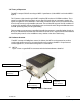
4.1.1 MDT-A Connectors 4.1.1.1 RF Output The RF Output connector is an SMA female (Bulkhead). 4.1.1.2 Pin 1 2 3 4 5 6 7 8 9 10 11 12 13 14 15 16 17 18 100-M0074X1 I/O The ‘I/O’ connector is a male, high-density DB-44. It is used to provide the interface for external power, audio, analog video, USB and RS-232 signals. The MDT-A has a separate RS232 channel (labeled “Control” on the external breakout cable) for control and monitoring the unit.
19 20-30 31 32 33 34-36 37 38 39 USB Gnd Not connected RS232 Control Tx RS232 Control-Rx RS232 GND Not connected Audio right + Audio right Audio right line opt. 40 41 42 43 Audio right GND Audio left + Audio left Audio left line opt 44 Audio left GND Not applicable for MDT-A Not applicable for MDT-A Pin 39 is connected to pin 38 for audio right channel input impedance of 600 ohms , balance in (mic or line level).
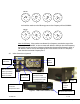
SW100 9 0 1 8 7 6 5 2 3 4 9 0 1 8 7 6 5 0 2 2 3 4 9 0 1 8 7 6 5 1 2 3 4 9 0 1 8 7 6 5 4 2 3 4 And with the switches in the following positions the frequency will read 924MHz: SW100 9 0 1 8 7 6 5 2 3 4 0 9 0 1 8 7 6 5 9 2 3 4 9 0 1 8 7 6 5 2 2 3 4 9 0 1 8 7 6 5 4 2 3 4 Note the following: if the switches are selected for a frequency outside the range of the frequency band of the MDT-A: the transmitter will default to the high side of the frequency band if the switches are set for a frequenc
If the MDT-A transmitter is used in the inline camera unit, analog audio and video functions are not provided. The DB-15 connector and J7 (ASI input) available only. 4.2.1 MDT Inline Camera Mount Connectors There are four BNC connectors, two audio XLR, one DB-15 connector, one N type connector and one rocker on/off power switch located on the MDT-A inline camera unit for interfacing the RF, audio, video, power and RS-232 signals. An optional LCD control front panel is also available.
4.2.1.3 Video Input (Not applicable to MDT-A) The MDT in-line camera enclosure uses female BNC connectors for video input. Component, Composite or S-Video input is accepted (see section 6 for setting video input type). J3 BNC connector marked “Y/COMP” is a dual use input connector; a) Composite Video or b) Luminance when used with Component video.
4. The GMS_MDT Setup program will prompt the user to click on the ‘computer icon’ button to begin installation. If desired, the user can change the destination directory from the default. Click on the ‘computer icon’ button. 5. The GMS_MDT Setup program will then prompt the user to ‘Choose Program Group’. If desired, the user can change the program group from the default. Click on the ‘Continue’ button. 6.
Figure 5 – MDT-A Configurator Main Screen 5.3.1 Function Buttons • “Enable All” Button: Clicking on this button enables all the check boxes on the screen. This operation is done to prepare all the fields to be written to (or read from). Alternatively, the end user can individually select a given field by using the mouse and clicking its corresponding check box. • “Disable All” Button: Clicking on this button disables all the check boxes on the screen.
to verify that a write operation has been correctly performed. An example scenario would be to 1) enable all fields, 2) change desired field(s), 3) perform a ‘Update’ (write) operation, 4) perform a ‘CLR’ operation and 5) perform a ‘Query’ operation. As a result of the ‘Query’ operation, the fields on the screen should all update to those values that were written during the ‘Update’ operation. • “Store All Setup Pages” Button: Clicking on this button will store all setup pages, even if they are not shown.
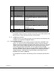
Field Input Mode 5.3.3 R/W R/W Video Input Video Locked Status R/W Audio Enable Audio Mute Audio Level Audio Gain - R Description least 10 % greater than the ASI stream rate. The MDT-A defaults to ASI only. No other selection is allowed. Not applicable. Video locked when an ASI stream is present. Yes,indicates Video is locked. No, not locked.
Video Profile - Pull down box offers a choice between the SP@ML profile (default profile) and the MP@ML profile. GOP Length- Group of pictures size (1-19) can be adjusted by selecting various values from the pull down boxes. Ctrl Port Baud Rate- The control port baud rate menu allows different baud rates to be selected when attached to the PC RS232 port. 115200-baud rate is the default value.
Figure 7 - Channel Rate Guide Figure 8 - FW Version 100-M0074X1 17 of 24 www.cobham.
6.0 Getting Starte The standard MDT-A kit includes the following items: MDT-A transmitter unit MDT-A full breakout cable (GMS p/n 780-C0224) (Power, A/V, Data, Control interfaces) NOTE: Based on customer application GMS may deliver additional cables and antennas. Contact GMS for further information. The MDT-A is pre-configured by GMS prior to shipment (based on customer requirements), thus is ready to work “right out of the box”. 6.
1. Install omni-directional antennas onto the MDT-A RF output port and Down- Converter (D/C) RF input port. Note: Transmitters should not be powered on without a load. Doing so could cause the output PA to stop working. A proper heat sink is also required. 2. Attach the breakout cable (DB-44 end) to the MDT-A unit (if unit is mounted in an Inline Camera Mount Box this step does not apply). 3. Attach a RF cable from the D/C IF output port to RF in port of the receiver. 4.
Output Power: Up to100mW (programmable) [200mW on some models] Connector: SMA-F Note: Transmitters should not be powered on without a load. Doing so could cause the output PA to stop working. A proper heat sink is also required. 7.4 Modulation Modulation Type: COFDM w/ QPSK, 16 QAM , or 64 QAM. FEC: ½, 2/3, ¾, 7/8 Guard Intervals: 1/32, 1/16, 1/8, ¼ Spurious: 50dBc Number of C-OFDM Carriers: 2k C-OFDM MER: > -45dB Standard: DVB-T compliant 7.
transmitter frequency (MDT-A) is set for 2000MHz, then the MDR can be set for 2000 MHz (it automatically calculates the IF frequency based on pre-programmed LO information of the downconverter). The IF frequency changes as the RF frequency changes; the LO remains constant. On non-GMS commercial digital receiver it may be necessary to program the receiver with the IF frequency directly. The user may need to do the simple math to arrive at the IF frequency so that it can be entered into the receiver.
Power Switch for local BNC connector – IF frequency output RF N type connector DB-9 connector for local power Figure 10 - BDC Connectors Table 4 - DB-9 Connector Pin Out for the D/C Pin 1 3 2, 4-9 100-M0074X1 Signal +12Vdc GND NC Notes Power supply must be able to source at least 500mA. Voltage should not drop below +10Vdc. Power ground Not Connected 22 of 24 www.cobham.
9.0 Cable Losses 9.1 Coax Cable Cable losses must be taken into consideration if the D/C is located a great distance from the receiver. As mentioned above long cable runs can contribute to more resistance in the lines and also can contribute to signal attenuation because of the additional capacitance. Even when using a good coax cable such as RG59/U the attenuation of the signal can be significant. For example, RG59/U coax will drop approximately 2dB per 100 feet at 50 MHz and 8 dB per 100 feet at 900 MHz.
Appendix A – Cable, MDT-A External Breakout REVISIONS NOTES: 1. REFERENCE BOM 780-C0224X2 FOR REFERENCE DESIGNATIONS (SHOWN AS [] ON DRAWING) AND PART DESCRIPTIONS . 2 LABEL FINAL CABLE ASSEMBLY WITH PART NUMBER 780-C0224X2 USING BEST COMMERCIAL METHOD. 3 LABEL CONNECTOR WITH REFERENCE DESIGNATOR AND DESCRIPTION AS SHOWN USING BEST COMMERCIAL METHOD. LABEL TO BE WITHIN 3.0 OF CONNECTOR. 4 REFERENCE MANUFACTURING INSTRUCTION 100-MI0112.