
User`s manual

100-M0058X2 12 of 13
www.cobham.com/gms
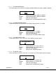
4.1 RF Output
The MDT inline camera enclosure uses a female N type connector (flange mount) for its
‘RF Output’ port.
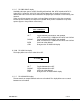
4.2 I/O
The ‘I/O’ connector is a female, DB-15. It is used to provide the interface for RS-232
signals (control and monitoring). GMS MDLB Configurator software program makes use
of the RS232 control lines, pins 2, 3 and 5 of the DB-15 connector. The RS-232 channel
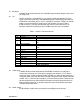
utilizes a 3-wire configuration. The pin out for I/O connector is shown in Table 2.
A USB connector is currently provided with the external serial cable which is an
alternate method of interfacing to the PC if DB-9 connectors are not available.
Table 1 - I/O DB-15 Connector Pin Out
Pin Signal Notes
1 +12Vdc
2 RS232-Rx (CTRL) Relative to MDT (i.e., control data is input on this pin)
3 RS232-Tx (CTRL) Relative to MDT (i.e., control data is output on this
pin)
4 Not connected
5 RS232-GND Common ground for both RS232 Data and Control
lines
6 I^2C_D
7 I^2C_C
8 USB Reset
+5Vdc
9 USB Data -
10 USB Data +
11 USB GND
12 Not connected
13 RS232-Tx (DATA)
Under development/for future updates
14 RS232-Rx (DATA)
Under development
15 RS232-GND
Under development
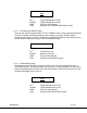
4.3 Video Input
The MDT–B inline camera enclosure uses female BNC connectors for video input.
Component, Composite or S-Video input is accepted (see section 3.1.3.5 for setting
video input type). J3 BNC connector marked “Y/COMP” is a dual use input connector; a)
Composite Video or b) Luminance when used with Component video. J2 BNC connector
marked “C/Pr” is a dual use input connector; a) Chroma when used with S-Video or b) Pr,
the red component minus the luminance information used with Component Video. J8
BNC connector marked “Pb” is the blue component minus the luminance information
used with Component Video.
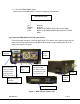
4.4 Power Switch
An LED indicator rocker switch is provided for controlling power to the unit.