
User`s manual

100-M0058X2 11 of 13
www.cobham.com/gms
3.1.3.10 EXIT DETAIL MENU display
Allows user to exit to Main Menu or to return to beginning of Detail Menu.
UP ↑ No effect
DOWN ↓ No effect
ENTR Returns to EXIT MDT-B CTRL display of Main Menu
CTRL Returns to TX COFDM MODE display, beginning of Detail
Menu.
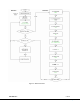
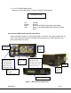
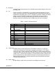
4.0 Connectors/PWR Switch and LCD Control Panel
There are four BNC connectors, two audio XLR, one DB-15 connector, one N type connector and one
rocker on/off power switch located on the MDT-B inline camera unit for interfacing the RF, audio,
video, power and RS-232 signals.
Figure 3 - MDT-B Inline Camera Unit
EXIT DETAIL MENU
DB
-
15
Connector
BNC J3, Y/COMP
=Composite video
input. When used with
S or Component video
= Luminance input
BNC J2=Chroma C
video input when
used with S-video.
When used with
Component v
ideo =
BNC J7 = SDI
input.
Balance
audio,
A1&A2
RF out
Power
“on/off”
switch.
LCD panel with controls
BNC J8 = Pb when
used with
Component video.