User’s Manual The most important thing we build is trust. Inline Camera Mount - Broadcast Version - 100-M0058X2 06/18/09 Cobham Surveillance GMS Products 1916 Palomar Oaks Way Ste 100 Carlsbad, CA 92008 T: 760-496-0055 F: 760-496-0057 www.cobham.
TABLE OF CONTENTS 1.0 ACRONYMS................................................................................................................................................................... 3 2.0 INTRODUCTION .................................................................................................................................................... 4 3.0 FRONT CONTROL PANEL OPERATION ................................................................................................... 4 3.
1.0 Acronyms This section lists and describes the various acronyms used in this document. Name 16QAM 64 QAM A/V C-OFDM CVBS Y C Pr Pb FEC MDT-B MPEG NTSC PAL QPSK RF SDI TX 100-M0058X2 Meaning 16-state Quadrature Amplitude Modulation 64-state Quadrature Amplitude Modulation Audio/Video Coded Orthogonal Frequency Division Multiplexing Color video base band signal (Composite video).
2.0 Introduction The inline camera mount box is an optional housing (for the MDT-B transmitter) which mounts to a professional A/V camera. The housings are designed to use either Anton Bauer or IDX batteries. The two line LCD (liquid crystal display) provides visual readouts of transmitter frequency, analog video lock status, COFDM mode, COFDM bandwidth, transmitter guard interval, forward error correction (FEC), video input type, audio status, audio gain and backlight status.
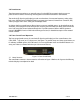
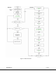
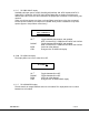
Figure 2 – Menu Flowchart 100-M0058X2 5 of 13 www.cobham.
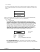
3.1.1 Power Up On power up the LCD displays the “GMS” logo and firmware number and then the “Initializing” display appears. It takes approximately 35 seconds before communications is established for the first time on power up. GMS RCU2000 G108 ↓ MDT-B IS INITIALIZING [Note: If communications cannot be established for some reason the LOST MDT-B COMM display appears. Re-try establishing communications by pressing the ENTR button.] 3.1.2 Main Menu 3.1.2.
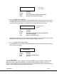
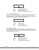
ENTER DETAIL MENU UP ↑ DOWN ↓ ENTR CTRL Enter detail menu display No effect No effect Enters detail menu TX COFDM MODE display Change to EXIT MDT-B CTRL display 3.1.2.3 Exit MDT-B Control Display This display allows user to either return to the CHANNEL display of the main menu or exit control of the MDT-B from the front LCD control panel. This is necessary when connecting to the camera mount housing through the DB-15 connector with a PC using GMS control software.
3.1.3.1 TX COFDM MODE display This display allows user to choose from three available COFDM modes, QPSK, 16QAM or 64QAM. TX COFDM MODE QPSK UP ↑ DOWN ↓ ENTR CTRL Toggles between QPSK, 16QAM and 64QAM Toggles between QPSK, 16QAM and 64QAM Saves new value selected Changes to the TX COFDM BANDWTH display 3.1.3.2 TX COFDM BANDWTH display COFDM bandwidth can be adjusted from this display selecting from 6, 7 or 8 MHz.
3.1.3.5 TX VIDEO INPUT display Available video input options are SDI (Serial Digital Interface), PAL, NTSC w/pedestal, NTSC, SVideo NTSC, S-Video PAL, YUV NTSC and YUV PAL. Depending on which input video type is selected the video source must be connected to the proper input connectors on the housing. See section 4. [Note: not all input options are shown in the pull down menu boxes unless the associated encoder profile is loaded.
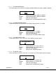
TX AUDIO LEVEL LINE UP ↑ DOWN ↓ ENTR CTRL Toggles between MIC or LINE Toggles between MIC or LINE Saves new value selected Changes to the TX AUDIO GAIN ADJUST display 3.1.3.8 TX AUDIO GAIN ADJUST display The audio gain can be adjusted with the ↑ UP and ↓ DOWN buttons. When adjusting the level the A1 letters on the left side will blink indicating that a change is in progress. If ENTR button is pressed the gain setting is stored.
3.1.3.10 EXIT DETAIL MENU display Allows user to exit to Main Menu or to return to beginning of Detail Menu. EXIT DETAIL MENU UP ↑ DOWN ↓ ENTR CTRL No effect No effect Returns to EXIT MDT-B CTRL display of Main Menu Returns to TX COFDM MODE display, beginning of Detail Menu. 4.
4.1 RF Output The MDT inline camera enclosure uses a female N type connector (flange mount) for its ‘RF Output’ port. 4.2 I/O The ‘I/O’ connector is a female, DB-15. It is used to provide the interface for RS-232 signals (control and monitoring). GMS MDLB Configurator software program makes use of the RS232 control lines, pins 2, 3 and 5 of the DB-15 connector. The RS-232 channel utilizes a 3-wire configuration. The pin out for I/O connector is shown in Table 2.
4.5 LCD Display Many of the control functions which are normally handled through the software interface and a PC are accessed directly with the front control panel and displayed on the LCD. 4.6 SDI Input (optional) A BNC connector is provided for Serial Digital Interface input data stream. 100-M0058X2 13 of 13 www.cobham.