
User`s manual


100-M0056X2B 25 of 28
www.cobham.com/gms
On non-GMS receivers it may be necessary to program the receiver with the IF frequency directly.
The user may have to do the simple math to arrive at the IF frequency so that it can be entered into
the receiver. The down-converter LO must be known. The math involve is as follows: “ LO –
transmitter frequency (or transmitter frequency – LO) = IF frequency”. For example, it the
transmitter is set for 2000MHz and the LO of the down-converter is 2800MHz then the IF
frequency is 800MHz (2800-2000 = 800). The receiver will need to be set to 800MHz to receive the
transmitter frequency of 2000MHz. Each time the transmitter frequency is changed the IF must be
re-calculated and entered into the receiver. It must also be mentioned, as you may have noticed
with the equation “LO-transmitter frequency or transmitter frequency – LO” that two answers are
possible. For example 2800-2000 = 800 or 2000-2800 = -800. The negative answer may indicate
the receiver wants the signal to be inverted. See section 6.3.3.2 for inverting the signal.
9.2 Local and Remote Power
Customers have the option of using remote or local power:
• Remote power is provided from the receiver through the BNC connector IF IN #1 located on the rear
panel (and IF IN #2 in the case of diversity systems with two down converters). IF PWR # 1 (and IF
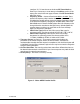
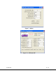
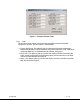
PWR #2 in case of diversity systems) needs to be switched ‘ON’. From the front control panel of the
receiver (MDR-B) toggle through the menus until “R1 BDC POWER DISPLAY’ (or “R2 BDC POWER
DISPLAY” in the case of diversity systems) is displayed. Ensure “ON” is selected (this the default mode
when shipped with D/C .The +12 Vdc provided from the receiver will travel through the coax cable to
the D/C.
If the D/C is located relatively close to the receiver then using remote power makes sense. However, if
the D/C is located at great distances away from the receiver there may be excessive DC voltage drop in
the coax cable (due to cable resistances). If this is the case then local DC power should be considered
as discussed below. If unsure of the DC voltage drop measure the DC voltage present (using a DMM) at
the end of the coax cable run. The D/C normal operating voltage is approximately +12 Vdc but can
operate down to +10 Vdc.
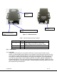
• Local power is provided by applying +12 Vdc to pin 1, GND to pin 3 of the DB-9 connector located on
the bottom of the D/C. The +12 Volt power supply must be able to source at least 500mA. The power
switch (located on the side of the D/C) enables the user to control the ‘ON’/’OFF’ positions for local
power. If using local power then the remote power IF IN #1 should be set to “OFF” (and RF IN #2 in
case of diversity systems).