
User`s manual

100-M0056X2B 12 of 28
www.cobham.com/gms
0
9 1
6
2
3
4
5
7
8
0
9 1
6
2
3
4
5
7
8
0
9 1
6
2
3
4
5
7
8
0
9 1
6
2
3
4
5
7
8
0
9 2 4
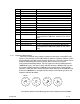
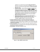
SW100
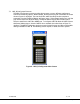
Note the following: if the switches are selected for a frequency outside the range of the
frequency band of the MDT-B: the transmitter will default to the high side of the frequency
band if the switches are set for a frequency higher than the transmitter frequency band. It
will default to the low side of the frequency band if the switches are set for a frequency
lower than the transmitter frequency band.
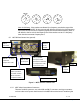
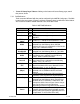
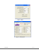
6.2 MDT-B Inline Camera Unit (optional)
Figure 3 - MDT-B Inline Camera Unit
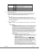
6.2.1 MDT Inline Camera Mount Connectors
There are four BNC connectors, two audio XLR, one DB-15 connector, one N type connector
and one rocker on/off power switch located on the MDT inline camera unit for interfacing the
DB
-
15
Connector
BNC J3, Y/COMP
=Composite video
input. When used with
S or Component video
= Luminance input
BNC J2=Chroma C
video input when
used with S-video.
When used with
Component video =
BNC J7 = SDI
or ASI input.
Balance
audio,
A1&A2
RF out
Power
“on/off”
switch.
LCD panel with controls
BNC J8 = Pb when
used with
Component video.