User’s Manual The most important thing we build is trust. Messenger Digital Transmitter (MDT-B) - Broadcast Version - 100-M0056X2B 05/28/09 Cobham Surveillance GMS Products 1916 Palomar Oaks Way Ste 100 Carlsbad, CA 92008 T: 760-496-0055 F: 760-496-0057 www.cobham.
Table of Contents 1.0 IMPORTANT WARNING AND GENERAL SAFETY INFORMATION........................................................ 4 2.0 ACRONYMS................................................................................................................................................................... 6 3.0 INTRODUCTION......................................................................................................................................................... 6 3.1 Key System Features .........
List of Tables Table 1 – Safe Distances .......................................................................................................................................................5 Table 2 - I/O DB-44 Connector Pin Out.......................................................................................................................10 Table 3 - I/O DB-15 Connector Pin Out.......................................................................................................................
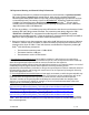
1.0 Important Warning and General Safety Information The following information is presented to the operator to ensure awareness of potential harmful RF (radio frequency) exposure and general hazards. With regards to potential harmful RF electromagnetic fields the text below is only a brief summary highlighting the possible risks and how to minimize exposure. The summary is based on OET Bulletin 65 “Evaluating Compliance with FCC Guidelines for Human Exposure to Radiofrequency Electromagnetic Fields” (1).
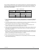
If any of the above variables change, such as a higher gain antenna, less or more power output from the transmitter, additional transmitters used, etc. then the safe distances would need to be recalculated. The user can either refer to the equations predicting RF Fields as noted in the above section or call contact GMS for advice at (760)-496-0055. Table 1 – Safe Distances Frequency = 1500 - MDTB Transmitter Power = 100,000 MHZ 0.
2.0 Acronyms This section lists and describes the various acronyms used in this document.
The Broadcast version of the MDL (Messenger Digital Link) provides professional Audio/Video (A/V) interfaces and processing. All versions of the MDL use a robust digital modulation system known as Coded Orthogonal Frequency Division Multiplexed (COFDM) that provides frequency diversity and powerful Forward Error Correction (FEC) algorithms.
NOTE: Based on customer application GMS may deliver additional cables and antennas. Contact GMS for further information. The MDT-B is pre-configured by GMS prior to shipment (based on customer requirements), thus is ready to work “right out of the box”. 5.1 Initial Checkout Prior to installing a MDT-B unit into the desired target environment, an initial checkout should be performed to ensure proper operation of the unit. The initial checkout consists of configuring a basic MDL-B link.
8. Apply power to the MDT-B and the MDR-B unit by attaching +12volts. To turn on the D/C, either 1) from the front control panel of the MDR-B toggle through the menus until “R1 (or R2 in the case of diversity systems) BDC POWER DISPLAY” is displayed. Ensure power is toggle “ON” (default mode is “ON” when shipped with down converters (D/C).
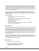
6.1.1 MDT-B Connectors There are three connectors located on the MDT-B unit as shown in Figure 2. They are for interfacing the RF, SDI/ASI, audio, video, power, RS-232 signals. 6.1.1.1 RF Output The MDT-B uses a female SMA bulkhead connector for its ‘RF Output’ port. Note: Transmitters should not be powered on without a load. Doing so could cause the output PA to stop working. 6.1.1.2 I/O The ‘I/O’ connector is a male, high-density DB-44.
6.1.2 15 16 17 18 19 20-29 30 Not connected USB power, Reset USB Data USB Data + USB Gnd Not connected PA_Shut_DN 31 32 33 34-36 37 38 39 RS232 Control Tx RS232 Control-Rx RS232 GND Not connected Audio right + Audio right Audio right line opt.
SW100 9 0 1 8 7 6 5 2 3 4 0 9 0 1 8 7 6 5 9 2 3 4 9 0 1 8 7 6 5 2 2 3 4 9 0 1 8 7 6 5 4 2 3 4 Note the following: if the switches are selected for a frequency outside the range of the frequency band of the MDT-B: the transmitter will default to the high side of the frequency band if the switches are set for a frequency higher than the transmitter frequency band. It will default to the low side of the frequency band if the switches are set for a frequency lower than the transmitter frequency band.
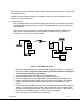
RF, audio, video, power and RS-232 signals. An optional LCD control front panel is also available. Inline camera mount is shown in Figure 3. 6.2.1.1 RF Output The MDT in line camera enclosure uses a female N type connector (flange mount) for its ‘RF Output’ port. Note: Transmitters should not be powered on without a load. Doing so could cause the output PA to stop working. 6.2.1.2 I/O The ‘I/O’ connector is a female, DB-15. It is used to provide the interface for RS-232 signals (control and monitoring).
BNC connector marked “Pb” is the blue component minus the luminance information used with Component Video. 6.2.1.4 Power Switch An LED indicator rocker switch is provided for controlling power to the unit. 6.2.1.5 LCD Display An optional LCD display with a front control panel is available for the inline camera mount unit.
7.3 MDL_B Configurator Functions The MDL_B Configurator program provides the user access to many different configuration, control and monitoring options. When the MDL_B Configurator program is launched, the screen shown in Figure 4 is displayed. The user should first select the serial port their computer is connected to via the Serial Port Selector and Status region. If the selected serial port is valid, the gray-colored status box will show ‘Ready’.
Figure 5 - MDT Configurator Main Screen 7.3.1 Function Buttons • “Enable All” Button: Clicking on this button enables all the check boxes on the screen. This operation is done to prepare all the fields to be written to (or read from). Alternatively, the end user can individually select a given field by using the mouse and clicking its corresponding check box. • “Disable All” Button: Clicking on this button disables all the check boxes on the screen.
• 7.3.2 “Store All Setup Pages” Button: Clicking on this button will store all setup pages, even if they are not shown. Field Definitions There are several different fields that can be configured by the MDT-B Configurator. The fields located in the main screen of Figure 5 and their associated values are defined in Table 3 below.
Field Audio Enable • 7.3.3 R/W Description Analog audio encoder enable. Desired mode of * R/W operation of the audio encoder is selected from the following values: Off or On. * Choice between mute or un-mute audio stream R/W Audio Mute * R/W Choice between mic or line level audio Audio Level * R/W Adjustable gain between 0- 100 Audio Gain Not applicable for embedded audio applications.
(see figure 7a). To have the unit in the desired RF Power Mode on Power up, it is necessary to store settings in the Others window. If the settings are stored in the main page, the state of the RF Power Mode will not be saved. Frequency switch – choices offered are enabled or disabled. These are the four frequency select switches discussed under section 5.1.1.3.
Figure 7 - Others Figure 7a – RF Power Off 100-M0056X2B 20 of 28 www.cobham.
Figure 8 - Transport Stream Setup 7.3.3.3 Help This pull-down menu contains information about the MDT firmware and the MDL Configurator software. This information is outlined below: Channel Rate Guide: This selection pulls up a table which displays the relationship between the Modulation mode, Modulation Guard Interval and FEC mode. Table values will change depending on COFDM Bandwidth selected. See figure 9.
Figure 9 - Channel Rate Guide Figure 10 - FW Version 100-M0056X2B 22 of 28 www.cobham.
8.0 Specifications The following sections outline the overall specifications for the MDT unit. 8.
Output Power: Up to100mW (programmable) [200mW on some models] Connector: SMA-F Note: Transmitters should not be powered on without a load. Doing so could cause the output PA to stop working. A proper heat sink is also required. 8.6 Modulation Modulation Type: COFDM w/ QPSK, 16 QAM or 64 QAM FEC: ½, 2/3, ¾, 7/8 Guard Intervals: 1/32, 1/16, 1/8, 1/4 Spurious: 50dBc Number of C-OFDM Carriers: 2k C-OFDM MER: > -45dB Standard: DVB-T compliant 8.
On non-GMS receivers it may be necessary to program the receiver with the IF frequency directly. The user may have to do the simple math to arrive at the IF frequency so that it can be entered into the receiver. The down-converter LO must be known. The math involve is as follows: “ LO – transmitter frequency (or transmitter frequency – LO) = IF frequency”. For example, it the transmitter is set for 2000MHz and the LO of the down-converter is 2800MHz then the IF frequency is 800MHz (2800-2000 = 800).
Power Switch for local RF Input BNC connector – IF frequency output DB-9 connector for local power Figure 11 - BDC Connectors Table 5 - DB-9 Connector Pin Out for the D/C Pin 1 3 2, 4-9 10.0 Signal +12Vdc GND NC Notes Power supply must be able to source at least 500mA. Voltage should not drop below +10Vdc. Power ground Not Connected Cable Losses 10.1 Coax Cable Cable losses must be taken into consideration if the D/C is located a great distance from the receiver.
Table 6 - RG59/U Coax Cable Losses • Belden cable # 1426A 100-M0056X2B 27 of 28 www.cobham.
Appendix A – Cable, MDT-B External Breakout for Broadcast Version REVISIONS NOTES: 1. REFERENCE BOM 780-C0224X2 FOR REFERENCE DESIGNATIONS (SHOWN AS [] ON DRAWING) AND PART DESCRIPTIONS . 2 LABEL FINAL CABLE ASSEMBLY WITH PART NUMBER 780-C0224X2 USING BEST COMMERCIAL METHOD. 3 LABEL CONNECTOR WITH REFERENCE DESIGNATOR AND DESCRIPTION AS SHOWN USING BEST COMMERCIAL METHOD. LABEL TO BE WITHIN 3.0 OF CONNECTOR. 4 REFERENCE MANUFACTURING INSTRUCTION 100-MI0112.