
User's Guide
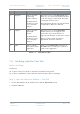
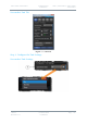
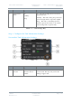

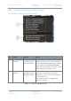

Table Of Contents
- 0. Preface
- 1. Systems Description
- 2. Getting Started
- 2.1 Identifying your Device
- 2.2 Unpacking your Nano Transmitter
- 2.3 Unpacking your HD Nano Transmitter
- 2.4 About the Labels on your Nano Transmitter
- 2.5 Planning the Hardware Installation
- 2.6 Identifying the Variants of Nano Transmitter
- 2.7 Identifying the Options of Nano Transmitter
- 2.1 Identifying the Variants of HD Nano Transmitter
- 2.2 Identifying the Options of HD Nano Transmitter
- 2.3 About the Software with your Nano Transmitter
- 3. Controls, Connections and Indicators
- 3.1 About Controls, Connections and Indicators
- 3.2 Exploring the Top Panel – Nano Transmitter
- 3.3 Exploring the Bottom Panel – Nano Transmitter
- 3.4 Exploring the Side Panel – Nano Transmitter
- 3.5 Exploring the Top Panel – HD Nano Transmitter
- 3.6 Exploring the Bottom Panel – HD Nano Transmitter
- 3.7 Exploring the Side Panel – HD Nano Transmitter
- 4. Setting up your Nano Transmitter
- 5. Basic Operation
- 6. Advanced Operation
- 7. Advanced Setup
- 7.1 About Advanced Setup
- 7.2 Installing the Nano TX Controller on your PC
- 7.3 Connecting your PC to the Nano TX using Serial
- 7.4 Exploring the Nano TX Controller Main Window
- 7.5 Performing a Quick Setup
- 7.6 Working with the Unit Status Panel
- 7.7 Working with the Switch Panel
- 7.8 Working with the Unit Tab
- 7.9 Working with the Modulation Tab
- 7.10 Working with the Audio Tab
- 7.11 Working with the Video Tab
- 7.12 Working with the Misc Tab
- 8. Appendix A – Cautions and Warnings
- 9. Appendix B - Care and Maintenance
- 10. Appendix C-Glossary
- 11. Appendix D – Reference Material

Solo7 Nano Transmitter
Commercial in
Confidence
Video, Transmitters, Solo7 Nano
Transmitter
100145
Revision: 8.0
Commercial in
Confidence
Page 7-48
No
Name
Options
Notes
2
Serial Number
cc7964a6
The Electronic Serial Number of the unit.
We may ask you for this during a support
call.
The licence file is specially configured to
only work with a device that has a
matching Electronic Serial Number. This
means the licence can only be used with
the actual hardware device for which it is
intended.
3
Base Card Info
100150 (D1515 L-
Band 1000-
1500MHz).
The frequency band details for the RF card
in the unit. See
Getting Started, Identifying
the Variants
for more versions.
4
Temperature
Any temperature in
degrees Celsius.
0 to 59 shown in green.
60 to 84 shown in yellow.
85 or above shown in red.
An indication of the temperature of the
FPGA. Attempt to keep it green.
CAUTION: If it changes to red, switch the
unit off and allow it to cool.
5
FPGA Version
07210001 or any
valid version
number.
The version of FPGA firmware currently
running on the D1500 board. We may ask
for this number during a support call.
6
Copy to
Clipboard
Button
Click to copy
contents of the
field to your
Windows clipboard.
If you need to gather some data about the
unit these buttons make it simple to get a
copy of the field onto your clipboard. Then,
you can paste it into a Word document for
example. You’ll find these buttons on most
fields in the Nano TX Controller.
Table 7-6 – Unit Information Settings Key