
User's Guide
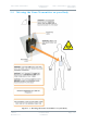
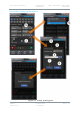
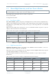
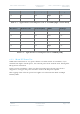
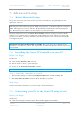
Table Of Contents
- 0. Preface
- 1. Systems Description
- 2. Getting Started
- 2.1 Identifying your Device
- 2.2 Unpacking your Nano Transmitter
- 2.3 Unpacking your HD Nano Transmitter
- 2.4 About the Labels on your Nano Transmitter
- 2.5 Planning the Hardware Installation
- 2.6 Identifying the Variants of Nano Transmitter
- 2.7 Identifying the Options of Nano Transmitter
- 2.1 Identifying the Variants of HD Nano Transmitter
- 2.2 Identifying the Options of HD Nano Transmitter
- 2.3 About the Software with your Nano Transmitter
- 3. Controls, Connections and Indicators
- 3.1 About Controls, Connections and Indicators
- 3.2 Exploring the Top Panel – Nano Transmitter
- 3.3 Exploring the Bottom Panel – Nano Transmitter
- 3.4 Exploring the Side Panel – Nano Transmitter
- 3.5 Exploring the Top Panel – HD Nano Transmitter
- 3.6 Exploring the Bottom Panel – HD Nano Transmitter
- 3.7 Exploring the Side Panel – HD Nano Transmitter
- 4. Setting up your Nano Transmitter
- 5. Basic Operation
- 6. Advanced Operation
- 7. Advanced Setup
- 7.1 About Advanced Setup
- 7.2 Installing the Nano TX Controller on your PC
- 7.3 Connecting your PC to the Nano TX using Serial
- 7.4 Exploring the Nano TX Controller Main Window
- 7.5 Performing a Quick Setup
- 7.6 Working with the Unit Status Panel
- 7.7 Working with the Switch Panel
- 7.8 Working with the Unit Tab
- 7.9 Working with the Modulation Tab
- 7.10 Working with the Audio Tab
- 7.11 Working with the Video Tab
- 7.12 Working with the Misc Tab
- 8. Appendix A – Cautions and Warnings
- 9. Appendix B - Care and Maintenance
- 10. Appendix C-Glossary
- 11. Appendix D – Reference Material

Solo7 Nano Transmitter
Commercial in
Confidence
Video, Transmitters, Solo7 Nano
Transmitter
100145
Revision: 8.0
Commercial in
Confidence
Page 6-31
6.3 About High Linearity and Low Power Modes
CAUTION: The combination of 100mW output power and High Linearity Mode must only be
used with additional cooling, either extra heat sinking or a fan.
The SOLO7 Nano Transmitter has two modes of operation:
Low Power Mode
High Linearity Mode
6.3.1 Low Power Mode
Low Power Mode optimises DC power consumption but to do this it must compromise the
quality of the COFDM waveform ‘shoulders’. This compromising of the shoulders often makes
little difference operationally when you just need to get a short range link in a reasonable RF
environment.
What Low Power Mode
does
do however is save a considerable amount of power so you can
deploy a unit on batteries for extended times.
Take a look at these power consumption figures when in Low Power Mode:
RF Output Power
VHF / UHF
L-Band
S-Band
10mW
3.1W
3.3W
3.4W
50mW
3.4W
3.6W
3.7W
100mW
3.7W
3.9W
4W
Table 6-1 – Typical Power Consumption in Low Power Mode
6.3.2 High Linearity Mode
High Linearity Mode optimises the quality of the COFDM waveform ‘shoulders’ , but to do
this it must increase DC power consumption.
This mode can be very useful when you are using an external amplifier which always expects
very high quality shoulders to work at its best.
Also, in busy RF environments you’ll need excellent shoulders to reject adjacent channel
interference.
Take a look at these charts to make a comparison between the modes:
DC Power
RF Power Out
Current I(mA)
Mode
Wattage
10
20
395
Low
3.95
10
17
330
Low
3.30
10
10
300
Low
3.00
10
20
455
High
4.55