9084 HD/SD-SDI RGB Color Corrector with YCbCr Video Proc and Frame Sync Product Manual Cobalt Digital Inc. 2406 E. University Ave. Urbana, IL 61802 Voice 217.344.1243 • Fax 217.344.1245 www.cobaltdigital.com 9084-OM (V4.
Copyright ©Copyright 2009, Cobalt Digital Inc. All Rights Reserved. Duplication or distribution of this manual and any information contained within is strictly prohibited without the express written permission of Cobalt Digital Inc. This manual and any information contained within, may not be reproduced, distributed, or transmitted in any form, or by any means, for any purpose, without the express written permission of Cobalt Digital Inc.
Table of Contents Chapter 1 Chapter 2 9084-OM (V4.0) Introduction . . . . . . . . . . . . . . . . . . . . . . . . . . . . . . . . . . . . . . . . . . . 1-1 Overview ................................................................................................................ 9084 Card Software Versions and this Manual ...................................................... Manual Conventions...............................................................................................
Chapter 3 Operating Instructions . . . . . . . . . . . . . . . . . . . . . . . . . . . . . . . . . . . 3-1 Overview ................................................................................................................. Control and Display Descriptions ........................................................................... Function Submenu/Parameter Submenu Overview .................................... 9084 Card Edge Controls, Indicators, and Display.....................................
Chapter 1 Chapter 1 Introduction Overview This manual provides installation and operating instructions for the 9084 HD/SD-SDI RGB Color Corrector with YCbCr Video Proc and Frame Sync card (also referred to herein as the 9084). This manual consists of the following chapters: • Chapter 1, “Introduction” – Provides information about this manual and what is covered. Also provides general information regarding the 9084.
1 9084 Card Software Versions and this Manual 9084 Card Software Versions and this Manual When applicable, Cobalt Digital Inc. provides for continual COMPASS™ card product enhancements through software updates. As such, functions described in this manual may pertain specifically to cards loaded with a particular software build. If you received your 9084 and this manual at the same time, this manual reflects all facets of your card. This manual (9084-OM (V4.
Introduction Manual Conventions Manual Conventions In this manual, display messages and connectors are shown using the exact name shown on the 9084 itself. Examples are provided below. • Card-edge display messages are shown like this: E201 • Connector names are shown like this: SDI IN In this manual, the terms below are applicable as follows: • 9084 refers to the 9084 HD/SD-SDI RGB Color Corrector with YCbCr Video Proc and Frame Sync card.
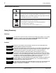
1 Safety Summary Labeling Symbol Definitions Attention, consult accompanying documents. Electronic device or assembly is susceptible to damage from an ESD event. Handle only using appropriate ESD prevention practices. If ESD wrist strap is not available, handle card only by edges and avoid contact with any connectors or components. Symbol (WEEE 2002/96/EC) For product disposal, ensure the following: • Do not dispose of this product as unsorted municipal waste. • Collect this product separately.
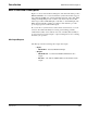
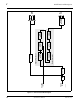
Introduction 9084 Functional Description 9084 Functional Description Figure 1-1 shows a functional block diagram of the 9084. The 9084 provides HD/SD-SDI RGB color correction with frame synchronization that supports all popular SD and HD video formats including 525i, 625i, 720p, 720f, 1080i, 1080p, and 1080psF. Input video format is auto-detected by the card. The 9084 accepts either an HD SDI input (1.485 Gbit) or an SD SDI input (270 Mbit) and automatically equalizes for cable loss.
1-6 9084 PRODUCT MANUAL 9084V4.0BD HD/SD SDI IN EXT REF IN (1,2) EQ Deserialize Color Corrector RGB Correction Video Processing Video Processor Reclock YCbCr Proc Frame Sync YCbCr Limiting AFD Insertion Serializer/ Cable Drivers SDI OUT RCK OUT 1 9084 Functional Description Figure 1-1 9084 Functional Block Diagram 9084-OM (V4.
Introduction 9084 Functional Description Color Corrector The 9084 color corrector converts the YCbCr SDI input video to the 4:4:4 RGB color space (where the color correction is applied), and then back to YCbCr SDI on the output. Controls are available to adjust each RGB level independently for both white levels (gain) and black levels (offset). Gamma can also be independently adjusted for each RGB channels. Various controls can be ganged to provide adjustment for all three color channels simultaneously.
1 9084 Functional Description User Control Interface Figure 1-2 shows the user control interface options for the 9084. These options are individually described below. Note: All user control interfaces described here are cross-compatible and can operate together as desired. Where applicable, any control setting change made using a particular user interface is reflected on any other connected interface.
Introduction 9084 Functional Description • Note: Built-in Card Edge User Interface – Using the built-in card edge controls and display, card control settings can be set using a front panel menu which is described in Chapter 3,“Operating Instructions”. Some of the 9084 functions described in this manual are available only when using the DashBoard™, or Cobalt® OGCP-9000 or OGCP-9000/CC Control Panels user interfaces.
1 9084 Functional Description Note: Although the OGCP-9000 Remote Control Panel can be used with the 9084, the OGCP-9000/CC Remote Control Panel is specifically designed for use with 9084 cards and provides the most intuitive and simplest interface of all the methods described. 9084 Rear I/O Modules The 9084 physically interfaces to system video connections at the rear of its frame using a Rear I/O Module.
Introduction Technical Specifications Technical Specifications Table 1-2 lists the technical specifications for the 9084 HD/SD-SDI RGB Color Corrector with YCbCr Video Proc and Frame Sync card. Table 1-2 Technical Specifications Item Characteristic Part number, nomenclature 9084 HD/SD-SDI RGB Color Corrector with YCbCr Video Proc and Frame Sync Installation/usage environment Intended for installation and usage in frame meeting openGear™ modular system definition.
1 Technical Specifications Table 1-2 Technical Specifications — continued Item Serial Digital Video Input (cont.) Characteristic SD Frame Rates Supported: 486i 29.97 (NTSC) 575i 25 (PAL) Impedance: 75 Ω terminating Equalization (HD): 328 ft (100 m) Belden 1694A Equalization (SD): 1000 ft (305 m) Belden 1694A Return Loss: > 15 dB at 5 MHz – 1.
Introduction Table 1-2 Technical Specifications Technical Specifications — continued Item Pre-Processor (Reclocked) Serial Digital Video Outputs (cont.) Characteristic Return Loss: > 15 dB at 5 MHz – 270 MHz > 12 dB at 270 MHz – 1.485 GHz Signal Level: 800 mV ± 10% DC Offset: 0 V ± 50 mV Jitter (HD): < 0.15 UI (all outputs) Jitter (SD): < 0.10 UI (all outputs) Overshoot: < 0.
1 Warranty and Service Information Warranty and Service Information Cobalt Digital Inc. Limited Warranty This product is warranted to be free from defects in material and workmanship for a period of five (5) years from the date of shipment to the original purchaser, except that 4000, 5000, 6000, 8000 series power supplies, and Dolby® modules (where applicable) are warranted to be free from defects in material and workmanship for a period of one (1) year. Cobalt Digital Inc.
Introduction Contact Cobalt Digital Inc. Contact Cobalt Digital Inc. Feel free to contact our friendly and professional support representatives for any of the following: 9084-OM (V4.0) • Name and address of your local dealer • Product information and pricing • Technical support • Upcoming trade show information Phone: (217) 344-1243 Fax: (217) 344-1245 Web: www.cobaltdigital.com General Information: info@cobaltdigital.com Technical Support: support@cobaltdigital.
This page intentionally blank 1-16 9084 PRODUCT MANUAL 9084-OM (V4.
Chapter 2 Chapter 2 Installation and Setup Overview This chapter contains the following information: • Installing the 9084 Into a Frame Slot (p. 2-1) • Installing a Rear I/O Module (p. 2-3) • Setting Up 9084 Network Remote Control (p. 2-4) Installing the 9084 Into a Frame Slot CAUTION Heat and power distribution requirements within a frame may dictate specific slot placement of cards.
2 Installing the 9084 Into a Frame Slot Note: • If installing the 9084 in an 8310-C-BNC or 8310-BNC frame (which is pre-equipped with a 100-BNC rear I/O module installed across the entire backplane) or a slot already equipped with a suitable I/O module, proceed to card installation steps below. • If installing the 9084 in a slot with no rear I/O module, an optional RM-9084-A Rear I/O Module is required before cabling can be connected.
Installation and Setup Note: Installing a Rear I/O Module To remove a card, press down on the ejector tab to unseat the card from the rear I/O module mating connector. Evenly draw the card from its slot. 10. Note: If network remote control is to be used for the frame and the frame has not yet been set up for remote control, perform setup in accordance with Setting Up 9084 Network Remote Control (p. 2-4).
2 Setting Up 9084 Network Remote Control 1 Align and engage mounting tab on Rear I/O Module with the module seating slot on rear of frame chassis. DSCN3483A.JPG 2 Hold top of Rear I/O Module flush against frame chassis and start the captive screw. Lightly tighten captive screw. DSCN3487A.JPG Figure 2-2 Rear I/O Module Installation Setting Up 9084 Network Remote Control Perform remote control setup in accordance with Cobalt® reference guide “COMPASS™ Remote Control User Guide” (PN 9000RCS-RM).
Chapter 3 Chapter 3 Operating Instructions Overview This chapter contains the following information: • Control and Display Descriptions (p. 3-1) • Accessing the 9084 Card via Remote Control (p. 3-10) • Checking 9084 Card Information (p. 3-12) • Ancillary Data Line Number Locations and Ranges (p. 3-13) • 9084 Function Submenu List and Descriptions (p. 3-14) • Color and Video Correction Examples Using the 9084 (p. 3-27) • Troubleshooting (p.
3 Control and Display Descriptions Note: Instructions provided here are applicable for all available user control methods. However, DashBoard™ and the Remote Control Panel provide greatly simplified user interfaces as compared to using the 9084 card edge controls. For this reason, it is strongly recommended that DashBoard™ or a Remote Control Panel be used for all 9084 applications other than the most basic cases.
Operating Instructions Control and Display Descriptions 9084 Card Edge Controls, Indicators, and Display Figure 3-2 shows and describes the 9084 card edge controls, indicators, and display.
3 Control and Display Descriptions 9084 Card Edge Control Menu/Submenu Structure (See below.) Using the menu system of group menus and submenus described earlier, the 9084 parameters/controls are organized into menus and submenus. As appropriate, a submenu similarly may have its own further additional subordinate submenus.
Operating Instructions Control and Display Descriptions Select a top-level menu item (in this example, select Vid (Video Proc and Color Correction controls)) Vid Submenu Depth 1 A B 2 Press Enter Menu and in this example, select ClrC (Color Correction). This selects the color correction function. Press Enter Menu again and in this example, select Enbl (Enable). Enbl On Off Press Exit Menu and in this example, select GAIN. This allows selection of an RGB channel gain control.
3 Control and Display Descriptions Card Edge Display Orientation, Brightness, and Timeout Adjust The card edge 4-Character Alphanumeric Display can be changed between vertical or horizontal character orientation to suit the mounting position of the card as shown and described below. D i s p D i s p 9084 9084 Vertical orientation displays characters as shown above (in this example, “Disp”). Use this orientation when a frame has cards positioned vertically.
Operating Instructions Control and Display Descriptions The timeout period from when a menu is entered to when the display times outs (reverts to the default card model display) can be adjusted from 5 to 9999 seconds (166.7 minutes) as described below. 1. Access the Displ (Display) menu. 2. Use the up/down switch to enter the desired timeout value as shown below. Card Edge Control Menu: Disp 1 2 TOUT (value) Timeout value (in seconds) DashBoard™ User Interface (See Figure 3-5.
3 Control and Display Descriptions Set Enable to On [ B – C in Figure 3-3] Select top-level menu item Color Correction [ A in Figure 3-3] Set Offset for Red channel (Black Adj. Red) to -10.0 using direct numeric entry or slider control [ G – I in Figure 3-3] Set Gain for Blue channel (White Adj. Blue) to 94.0 using direct numeric entry or slider control [ D – F in Figure 3-3] 9084_CC_EX1.PNG Figure 3-5 DashBoard™ Setup of Example Color Correction Function 3-8 9084 PRODUCT MANUAL 9084-OM (V4.
Operating Instructions Control and Display Descriptions Cobalt® Remote Control Panel User Interfaces (See Figure 3-6.) Similar to the function submenu tabs using DashBoard™, the Remote Control Panels have a Select Submenu key that is used to display a list of function submenus. From this list, a control knob on the Control Panel is used to select a function from the list of displayed function submenu items.
3 Accessing the 9084 Card via Remote Control Accessing the 9084 Card via Remote Control Access the 9084 card using DashBoard™ or Cobalt® Remote Control Panel as described below. Accessing the 9084 Card Using DashBoard™ 1. On the computer connected to the frame LAN, open DashBoard™. 2. As shown below, in the left side Basic View Tree locate the Network Controller Card associated with the frame containing the 9084 card to be accessed (in this example, “MFC-8310-N SN: 00108053”). DB_ACCESS1.PNG 3.
Operating Instructions Card Access/Navigation Tree Pane Accessing the 9084 Card via Remote Control Card Info Pane Card Function Submenu and Controls Pane 9084_DB_ACCESS2A3V4.PNG Accessing the 9084 Card Using a Cobalt® Remote Control Panel Press the Select Device key and select a card as shown in the example below. OGCP-CC3_3422A.JPG The display shows the list order number of the device that is ready for selection The display shows the devices assigned to the Control Panel.
3 Checking 9084 Card Information Checking 9084 Card Information The operating status and software version the 9084 card can be checked using the card edge control user interface or DashBoard™. Figure 3-7 shows and describes the 9084 card information screen using DashBoard™ and accessing card information using the card edge control user interface. Note: Proper operating status in DashBoard™ is denoted by green icons for the status indicators shown in Figure 3-7.
Operating Instructions Ancillary Data Line Number Locations and Ranges Ancillary Data Line Number Locations and Ranges Table 3-1 lists the default output video VANC line number locations for various ancillary data items processed or passed by the card. Table 3-1 9084 Ancillary Data Line Number Locations/Ranges Default Line No.
3 9084 Function Submenu List and Descriptions 9084 Function Submenu List and Descriptions Table 3-2 individually lists and describes each 9084 function submenu “tab” and its related list selections, controls, and parameters. Where helpful, examples showing usage of a function are also provided. Table 3-2 is primarily based upon using DashBoard™ to access each function and its corresponding submenus and parameters.
Operating Instructions Table 3-2 9084 Function Submenu List and Descriptions 9084 Function Submenu List Provides the following Video Proc parametric controls. • Video Proc Video Proc (On/Off) provides master on/off control of all Video Proc functions. • When set to Off, Video Proc is bypassed. • When set to On, currently displayed parameter settings take effect.
3 Table 3-2 9084 Function Submenu List and Descriptions 9084 Function Submenu List — continued (continued) • Color Gain Adjusts gain percentage (saturation) applied to Chroma (C-channel). (0% to 200% range in 0.1% steps; unity = 100%) Card Edge Control Menu: Vid 1 2 3 Proc Sat (sat value) Color gain in percent • Color Phase Adjusts phase angle applied to Chroma. (-360° to 360° range in 0.
Operating Instructions Table 3-2 9084 Function Submenu List and Descriptions 9084 Function Submenu List — continued (continued) • White Hard Clip Applies white hard clip (limiting) at specified percentage. (50.0% to 109.1%; null = 109.1%) Card Edge Control Menu: Vid 1 2 3 4 Proc Clip WHCL (value) Clip value in percent; 0.1% precision • White Soft Clip Applies white soft clip (limiting) at specified percentage. (50.0% to 109.1%; null = 109.
3 9084 Function Submenu List and Descriptions Table 3-2 9084 Function Submenu List — continued Allows assignment of AFD (Active Format Description) codes to the SDI output video. AFD Note: This function only marks the SDI output with an AFD code. Actual AFD processing must be performed by a downstream card or system that recognizes an AFD code assigned here.
Operating Instructions Table 3-2 9084 Function Submenu List and Descriptions 9084 Function Submenu List — continued Provides color corrector functions for the individual RGB channels of the received SD/HD SDI signal. • Color Corrector Color Corrector (On/Off) provides master on/off control of all Color Corrector functions. • When set to Off, all processing is bypassed. • When set to On, currently displayed parameters settings take effect.
3 Table 3-2 9084 Function Submenu List and Descriptions 9084 Function Submenu List — continued (continued) • Gang Black Level Controls When set to On, changing any of the Black Adj. controls increases or decreases R, G, and B black levels by equal amounts. Card Edge Control Menu: Vid 1 2 3 4 ClrC OFFS GANG On Off Ganging On Ganging Off • White Adj. (Green – Red – Blue) Separate red, green, and blue gain controls respectively apply gain percentage for R, G, and B channels. (0.0 to 200.
Operating Instructions Table 3-2 9084 Function Submenu List and Descriptions 9084 Function Submenu List — continued (continued) • Gamma (Green – Red – Blue) Separate red, green, and blue gamma controls respectively apply gamma curve adjustment for R, G, and B channels. (0.125 to 8.000 range in thousandths steps; unity = 1.000) Card Edge Control Menu: Vid 1 2 3 4 ClrC GAMA GRN BLUE RED Select Green channel Select Blue channel Select Red channel (value) Gamma value in percent (0.
3 9084 Function Submenu List and Descriptions Table 3-2 9084 Function Submenu List — continued Provides video Frame Sync and delay control tools. Framesync • Framesync Enable Disables the Frame Sync function, or selects from choices below. • Off: Disables Frame Sync function; output video timing matches the input video timing. • Reference 1: Allows Frame Sync function to use external Reference 1 as the reference standard.
Operating Instructions Table 3-2 9084 Function Submenu List and Descriptions 9084 Function Submenu List — continued (continued) • Minimum Latency Frames Control Minimum Latency Frames Control When Framesync is enabled, specifies the smallest amount of latency allowed by the frame sync (latency measurement in output video frames). The frame sync will not output a frame unless the specified number of frames are captured in the buffer.
3 9084 Function Submenu List and Descriptions Table 3-2 9084 Function Submenu List — continued (continued) • Framesync LOS Freeze Color In the event of LOS with Freeze to Color enabled above, sets the image raster color from choices shown to the left. • Custom Color Hue Adjusts raster hue (phase angle) for custom LOS color. (-360° to 360° range in 0.1° steps; null = 0°) • Custom Color Saturation Adjusts raster saturation level for custom LOS color. (0% to 100% range in 0.
Operating Instructions Table 3-2 9084 Function Submenu List and Descriptions 9084 Function Submenu List — continued This function allows up to 16 card user settings configuration presets to be saved in a Preset and then recalled (loaded) as desired. All current settings (including list selections and scalar (numeric) control settings such as Gain, etc.) are saved when a Preset Save is invoked.
3 Table 3-2 9084 Function Submenu List and Descriptions 9084 Function Submenu List — continued (continued) • Reset Current Preset • Reset Current Preset resets all parameters (including preset custom name entered) of the currently selected Preset (as displayed in the Selected Preset field) to factory default settings. The above button has a Confirm? pop-up that appears, requesting confirmation.
Operating Instructions Color and Video Correction Examples Using the 9084 Color and Video Correction Examples Using the 9084 Shown below are examples of using the 9084 to provide parametric color and video correction. On-Set Monitor Color Correction Example A typical use for the 9084 Color Corrector function is to provide color correction for a monitor when an anchor desk set includes a monitor, as shown in Figure 3-9. In the example setup shown in Figure 3-9, a monitor is located behind the anchor desk.
3 Color and Video Correction Examples Using the 9084 Ideally, this display would essentially result in a waveform showing identical RGB components corresponding to the grayscale monochrome bar spectrum being fed to the set monitor. However, as shown in Figure 3-10 with no correction applied, the waveform monitor shows imbalance between the RGB channels due to the reasons discussed above. Note the excessive offset, level, and deviation from an ideal gamma curve for the blue channel.
Operating Instructions Color and Video Correction Examples Using the 9084 Figure 3-11 shows the same setup using the 9084 Color Corrector function, along with the appropriate signal source standard and a video waveform monitor to assess and determine the color correction required. In the calibration setup shown in Figure 3-11 the feed to the switcher is monitored by a WFM 7120 Waveform Monitor, with the set monitor being fed a monochrome linear limit ramp by a TG700 siggen.
3 Color and Video Correction Examples Using the 9084 Uncompensated Gain (Left) Noting that the uncompensated black offset for the blue channel is negative, a correspondingly equivalent positive setting is applied using the blue channel Black offset control (in this example, adjusting the Black offset from unity to 5.0 provides compensation).
Operating Instructions Color and Video Correction Examples Using the 9084 Miscellaneous Color and Video Correction Examples Table 3-3 provides examples showing and describing various color and video condition corrections using the 9084. Note: Table 3-3 Signal generator and waveform monitor used in these examples are Tektronix® models TG700 and WFM 7120, respectively.
3 Color and Video Correction Examples Using the 9084 Table 3-3 Color and Video Corrections Using the 9084 — continued Condition Observed On Waveform Monitor Correction Using 9084 White (luma) level exceeding 100% level (as shown below for limit ramp monochrome bars on waveform monitor display) Using the White Hard Clip control, a lowered white hard clipping threshold is applied to now limit the level to 100%. VAR4.PNG VAR4A.
Operating Instructions Table 3-3 Color and Video Correction Examples Using the 9084 Color and Video Corrections Using the 9084 — continued Condition Observed On Waveform Monitor Correction Using 9084 Chroma gain exceeds 100% level (as shown below for 100% color bars on YPbPr waveform monitor display) Using the Color Gain (Chroma) control to reduce chroma gain, chroma gain is now restored to 100% level. VAR10A.PNG VAR10.
3 Troubleshooting Troubleshooting This section provides general troubleshooting information and specific symptom/corrective action for the 9084 card. The 9084 card requires no periodic maintenance in its normal operation; if any error indication (as described in this section) occurs, use this section to correct the condition. Error and Failure Indicator Overview The 9084 card itself and its remote control systems all (to varying degrees) provide error and failure indications.
Operating Instructions Troubleshooting 9084 Card Edge Status/Error Indicators and Display Figure 3-13 shows and describes the 9084 card edge status indicators and display. These indicators and the display show status and error conditions relating to the card itself and remote (network) communications (where applicable).
3 Troubleshooting DashBoard™ Status/Error Indicators and Displays Figure 3-14 shows and describes the DashBoard™ status indicators and display. These indicator icons and displays show status and error conditions relating to the 9084 card itself and remote (network) communications.
Operating Instructions Troubleshooting Access Card Info panes for specific cards by clicking the card slot position in the Card Access/Navigation Tree pane (as shown in the example in Figure 3-15). Status for selected card is shown here (in this example, connection OK and “Fan Door Open” alert) By clicking on “Slot 0: MFC-8310-N” in this example, Card Info is displayed for frame Network Controller Card Card general information is displayed in lower portion of Card Info pane 9084_TS_CARD_INFO_ACCESS.
3 Troubleshooting Basic Troubleshooting Checks Failures of a general nature (affecting many cards and/or functions simultaneously), or gross inoperability errors are best addressed first by performing basic checks before proceeding further. Table 3-4 provides basic system checks that typically locate the source of most general problems. If required and applicable, perform further troubleshooting in accordance with the other troubleshooting tables in this section.
Operating Instructions Troubleshooting 9084 Processing Error Troubleshooting Table 3-5 provides 9084 processing troubleshooting information. If the 9084 card exhibits any of the symptoms listed in Table 3-5, follow the troubleshooting instructions provided. In the majority of cases, most errors are caused by simple errors where the 9084 is not appropriately set for the type of signal being received by the card.
3 Troubleshooting Table 3-5 Troubleshooting Processing Errors by Symptom — continued Symptom Error/Condition Corrective Action DashBoard™ shows Framesync Status error message in 9084 Framesync function submenu screen. Specified Minimum Latency Frames setting exceeds 9084 card buffer space for the selected output video format • Reduce the Minimum Latency Frames setting as specified in the error message to correct the error. Ancillary data (closed captioning, timecode, AFD, etc.
Cobalt Digital Inc. 2406 E. University Ave. Urbana, IL 61802 Voice 217.344.1243 • Fax 217.344.1245 www.cobaltdigital.com 9084-OM (V4.