9035 HD/SD-SDI – Analog In Frame Sync with Audio Embedding/De-Embedding and Dolby® Decoding Option Product Manual Cobalt Digital Inc. 2406 E. University Ave. Urbana, IL 61802 Voice 217.344.1243 • Fax 217.344.1245 www.cobaltdigital.com 9035-OM (V4.
Copyright ©Copyright 2013, Cobalt Digital Inc. All Rights Reserved. Duplication or distribution of this manual and any information contained within is strictly prohibited without the express written permission of Cobalt Digital Inc. This manual and any information contained within, may not be reproduced, distributed, or transmitted in any form, or by any means, for any purpose, without the express written permission of Cobalt Digital Inc.
Table of Contents Chapter 1 Chapter 2 9035-OM (V4.4) Introduction . . . . . . . . . . . . . . . . . . . . . . . . . . . . . . . . . . . . . . . . . . . 1-1 Overview ................................................................................................................ 9035 Card Software Versions and this Manual ...................................................... Cobalt Reference Guides ........................................................................................
Chapter 3 Operating Instructions . . . . . . . . . . . . . . . . . . . . . . . . . . . . . . . . . . . 3-1 Overview ................................................................................................................. 3-1 Control and Display Descriptions ........................................................................... 3-1 Function Submenu/Parameter Submenu Overview .................................... 3-2 DashBoard™ User Interface .....................................................
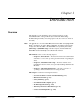
Chapter 1 Chapter 1 Introduction Overview This manual provides installation and operating instructions for the 9035 HD/SD-SDI – Analog In Frame Sync with Audio Embedding/ De-Embedding and Dolby® Decoding Option card (also referred to herein as the 9035). Note: This manual also covers the 9035-DEC, which is the 9035 card equipped with Dolby® decoding as an option.
1 9035 Card Software Versions and this Manual 9035 Card Software Versions and this Manual When applicable, Cobalt Digital Inc. provides for continual product enhancements through software updates. As such, functions described in this manual may pertain specifically to cards loaded with a particular software build. The Software Version of your card can be checked by viewing the Card Info menu in DashBoard™. See Checking 9035 Card Information (p.
Introduction Manual Conventions Manual Conventions In this manual, display messages and connectors are shown using the exact name shown on the 9035 itself. Examples are provided below. • Card-edge display messages are shown like this: Ch01 • Connector names are shown like this: AES IN 1 In this manual, the terms below are applicable as follows: • 9035 refers to the 9035 HD/SD-SDI – Analog In Frame Sync with Audio Embedding/De-Embedding and Dolby® Decoding Option card.
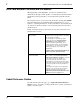
1 Safety Summary Labeling Symbol Definitions Attention, consult accompanying documents. Electronic device or assembly is susceptible to damage from an ESD event. Handle only using appropriate ESD prevention practices. If ESD wrist strap is not available, handle card only by edges and avoid contact with any connectors or components. Symbol (WEEE 2002/96/EC) For product disposal, ensure the following: • Do not dispose of this product as unsorted municipal waste. • Collect this product separately.
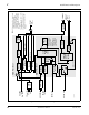
Introduction 9035 Functional Description 9035 Functional Description Figure 1-1 shows a functional block diagram of the 9035. The 9035 includes includes a full 16-channel audio embedder/de-embedder, a 12-bit analog-to-digital video converter, an 8-channel, 24-bit balanced analog-to-digital audio converter, and a full video frame synchronizer. The 9035 also handles timecode insertion, closed captioning support, and transfer of Dolby® metadata.
1-6 9035 PRODUCT MANUAL 9035V4.4BD AES I/O (1-4) AES IN (5-8) AN-AUD IN (1-8) HD/SD SDI IN Pb IN Pr/C IN Y/Cmpst IN EXT REF IN (1,2) (from frame) EQ/Deserialize Video A/D S11–S14 [AES IN (1-4)] Framesync Tracking Delay and User Offset Audio Routing/ Gain Control Audio LTC (NOTE 3) VBI Timecode (NOTE 2) 2.0-to-5.1 Upmixer Frame Sync AES Encode Audio Embed Active: Overwrites 6 selected channels with new 5.1 mix. See text. Bypass: Bypasses 2.0-to-5.
Introduction 9035 Functional Description Video Processor Description The 9035 video subsystem also provides the functions described below. Video Processor The 9035 provides full color processing control (luma gain and lift, chroma saturation, and color phase) of the output video. Frame Sync Function This function provides for frame sync control using either one of two external Ext.
1 9035 Functional Description HD/SD–SDI (From Video Proc) SDI VITC Timecode Proc/Embed SDI Video Input SDI VITC Detect/Extract Priority/ Select Buffer/ Format ATC_VITC Timecode Proc/Embed SDI ATC_VITC Detect/Extract ATC_LTC Timecode Proc/Embed SDI ATC_LTC Detect/Extract HD/SD–SDI Video Output Insert Control Line Number Control Audio/ RS-485 LTC Audio LTC Select/Extract Audio/RS-485 LTC Generate Audio LTC Out RS-485 LTC Out Figure 1-2 Timecode Processor Closed Captioning Inserter This functio
Introduction 9035 Functional Description Audio Processor Description The audio processor operates as an internal audio router.
1 9035 Functional Description As set with the default settings, the routing between embedded audio channels Embed Ch 1 thru Embed Ch 16 and discrete AES audio channels AES Ch1 thru AES Ch 16 is as shown in Figure 1-3. In this mode, the routing is basic 1-to-1 embedding/de-embedding for the 16 audio embedded and AES discrete audio channels. Other sources and/or destinations for each channel are selected (from the choices listed above) using the card edge controls or a remote control system.
Introduction 9035 Functional Description 2.0-to-5.1 Upmix Function Note: Upmix function is an optional licensable feature. This function and its controls appear only when a license key is entered and activated. (This option (identified in Cobalt® price lists as +UM) can be purchased upon initial order, or field-activated using a key string which is sent to you when this option is purchased.) The 2.0-to-5.
1 9035 Functional Description From Audio Routing/Gain Emb Ch 1 – Ch 16 Control > Threshold Detect Emb Ch 1 Emb Ch 2 With all detected signal levels on Emb Ch 3 – Ch 6 below threshold, upmixer is active and overwrites with new 5.1. Emb Ch 3 Emb Ch 4 Emb Ch 5 Emb Ch 6 - 20 dBFS - 60 dBFS L – Emb Ch 1 R – Emb Ch 2 L C – Emb Ch 3 R LFE – Emb Ch 4 (C) Ls – Emb Ch 5 (LFE) Rs – Emb Ch 6 (Ls) (Rs) Selected channels Emb Ch 1 – Ch 6 are overwritten with the new 5.1 upmix content.
Introduction 9035 Functional Description Loudness Processor (Option +LP) Note: Loudness processor function is an optional licensable feature. This function and its controls appear only when a license key is entered and activated. (This option (identified in Cobalt® price lists as +LP) can be purchased upon initial order, or field-activated using a key string which is sent to you when this option is purchased.) If your card was purchased with option +LP, loudness processor manual supplement “5.
1 9035 Functional Description 9035 Post-Production Video Feed (with four embedded audio channels) SDI OUT SDI IN Audio Embed Audio De-Embed OTA Video Feed (with six embedded audio channels) Audio Embed/ Routing Embed Ch 1 Embed Ch 2 Embed Ch 3 Embed Ch 4 Analog 2-Channel Voice-Over Feed AN-AUD IN 1 AN-AUD IN 2 AES OUT 1 AES Ch 3 AES Ch 4 AES OUT 2 AES Ch 5 AES Ch 6 AES OUT 3 Analog Ch 1 Analog Ch 2 AES IN 5 AES Ch 9 AES Ch 10 AES IN 6 AES Ch11 AES Ch 12 AES Ch 15 AES Ch 16 AES IN 8 AES
Introduction 9035 Functional Description Zero-DEClay Audio Embedding In cases where additional delay must be avoided, it may be desirable to embed AES with minimum latency. Using zero-DEClay embedding, the video can then be delayed by one frame to account for any remaining audio delay. In this manner, any delay between video and audio can be cleanly contained and managed within one frame period.
1 9035 Functional Description Dolby® Identification and Metadata Output Processing (See Figure 1-7.) All AES pairs and embedded channels are checked by the 9035-DEC for valid Dolby® status. When a valid Dolby® encoded embedded or discrete AES pair is detected, the channel pair carrying the Dolby® format is displayed as “Locked Dolby E” or “Locked Dolby Digital”, as applicable. (The decoder always uses the metadata associated with its respective AES pair.
Introduction 9035 Functional Description User Control Interface Figure 1-8 shows the user control interface options for the 9035. These options are individually described below. Note: All user control interfaces described here are cross-compatible and can operate together as desired. Where applicable, any control setting change made using a particular user interface is reflected on any other connected interface.
1 9035 Functional Description • Note: Built-in Card Edge User Interface – Using the built-in card edge controls and display, card control settings can be set using a front panel menu which is described in Chapter 3,“Operating Instructions”. Some of the 9035 functions described in this manual are available only when using the DashBoard™, or Cobalt® OGCP-9000 or OGCP-9000/CC Remote Control Panel user interfaces.
Introduction 9035 Functional Description 9035 Rear I/O Modules The 9035 physically interfaces to system video and audio connections using a Rear I/O Module. Figure 1-9 shows a typical 9035 Rear I/O Module. All inputs and outputs shown in the 9035 Functional Block Diagram (Figure 1-1) enter and exit the card via the card edge backplane connector.
1 9035 Functional Description Figure 1-10 shows a 9035 card using an RM-9035-B Rear I/O Module.
Introduction 9035 Functional Description Audio and Video Formats Supported by the 9035 The 9035 supports all current SMPTE standard SD and HD video formats. Table 1-1 lists and provides details regarding the audio and video formats supported by the 9035. Table 1-1 Supported Audio and Video Formats Item Description/Specification Input / Output Video Raster Structure: Frame Rate: 1080PsF 23.98; 24 1080p 23.98; 24 1080i (1) 25; 29.97; 30 720p 23.98 (2); 24 (2); 25; 29.97; 30; 50; 59.
1 Technical Specifications Technical Specifications Table 1-2 lists the technical specifications for the 9035 HD/SD Frame Sync with Audio Embedding/De-Embedding and Dolby® Decoding Option card.
Introduction Table 1-2 Technical Specifications Technical Specifications — continued Item Serial Digital Video Input (cont.) Characteristic Equalization (SD): 1000 ft (305 m) Belden 1694A Return Loss: > 18dB at 5 MHz – 1.
1 Technical Specifications Table 1-2 Technical Specifications — continued Item Serial Digital Video Outputs (cont.) Characteristic Return Loss: > 15 dB at 5 MHz – 270 MHz > 12 dB at 270 MHz – 1.485 GHz Signal Level: 800 mV ± 10% DC Offset: 0 V ± 50 mV Jitter (HD): < 0.15 UI (all outputs) Jitter (SD): < 0.06 UI (all outputs) Overshoot: < 0.2% of amplitude AES Audio Input Standard: SMPTE 276M Number of Inputs (maximum): 8 unbalanced Input Level: 0.1 to 2.
Introduction Table 1-2 Technical Specifications Technical Specifications — continued Item AES Audio Output (cont.) Characteristic Output Impedance: 75 Ω Return Loss: > 30 dB 100 kHz to 6 MHz Sample Rate: 48 kHz Audio/RS-485 LTC Support (+LTC option only) Balanced analog audio or AES/embedded PCM equivalent conforming to SMPTE 12M-1; § 9.
1 Technical Specifications Table 1-2 Technical Specifications — continued Item Reference Video Input Characteristic Number of Inputs: Two non-terminating (looping) Frame Reference inputs Standards Supported (HD): 720p 24; 25; 29.97; 30; 50; 59.94 1080i 25; 29.97 1080p 23.98; 24; 25; 29.97; 30 1080p/sF 23.98; 24 Standards Supported (SD): 486i 29.
Introduction Warranty and Service Information Warranty and Service Information Cobalt Digital Inc. Limited Warranty This product is warranted to be free from defects in material and workmanship for a period of five (5) years from the date of shipment to the original purchaser, except that 4000, 5000, 6000, 8000 series power supplies, and Dolby® modules (where applicable) are warranted to be free from defects in material and workmanship for a period of one (1) year. Cobalt Digital Inc.
1 Contact Cobalt Digital Inc. Contact Cobalt Digital Inc. Feel free to contact our friendly and professional support representatives for any of the following: 1-28 • Name and address of your local dealer • Product information and pricing • Technical support • Upcoming trade show information Phone: (217) 344-1243 Fax: (217) 344-1245 Web: www.cobaltdigital.com General Information: info@cobaltdigital.com Technical Support: support@cobaltdigital.com 9035 PRODUCT MANUAL 9035-OM (V4.
Chapter 2 Chapter 2 Installation and Setup Overview This chapter contains the following information: • Setting I/O Switches for AES I/O (1-4) Ports (p. 2-1) • Installing the 9035 Into a Frame Slot (p. 2-2) • Installing a Rear I/O Module (p. 2-4) • Setting Up 9035 Network Remote Control (p.
2 Installing the 9035 Into a Frame Slot Rear of Card AES I/O 4 AES I/O 3 AES I/O 2 AES I/O 1 S11 S12 S13 S14 INPUT MODE (Factory Default) OUTPUT MODE • • • • Figure 2-1 9035 AES I/O (1-4) Mode Switches Installing the 9035 Into a Frame Slot CAUTION Heat and power distribution requirements within a frame may dictate specific slot placement of cards.
Installation and Setup Note: Installing the 9035 Into a Frame Slot • If installing the 9035 in a slot already equipped with a suitable I/O module, proceed to card installation steps below. • If installing the 9035 in a slot with no rear I/O module, a Rear I/O Module is required before cabling can be connected. Refer to Installing a Rear I/O Module (p. 2-4) for rear I/O module installation procedure.
2 Installing a Rear I/O Module Note: External frame sync reference signals are received by the card over a reference bus on the card frame, and not on any card rear I/O module connectors. The frame has BNC connectors labeled REF 1 and REF 2 which receive the reference signal from an external source such as a house distribution. Note: The 9035 BNC inputs are internally 75-ohm terminated. It is not necessary to terminate unused BNC inputs or outputs.
Installation and Setup Installing a Rear I/O Module 1 Align and engage mounting tab on Rear I/O Module with the module seating slot on rear of frame chassis. DSCN3483A.JPG 2 Hold top of Rear I/O Module flush against frame chassis and start the captive screw. Lightly tighten captive screw. Note: Rear I/O Modules RM20-9035-C, -D, -E, and -F occupy two rear module slot mounting locations and use two captive screws.
2 Installing a Rear I/O Module Table 2-1 9035 Rear I/O Modules 9035 Rear I/O Module RM20-9035-A Description Provides the following connections: • HD/SD-SDI coaxial input (SDI IN) • Analog Y/composite, Pr/C, and Pb coaxial inputs (Y/Cmpst, Pr/C, and Pb, respectively) • Four AES I/O coaxial input/outputs (AES I/O 1 thru AES I/O 4; I/O function of each connection is user-configurable) • Two buffered SDI coaxial outputs (SDI OUT) RM20-9035-B Provides the following connections: • HD/SD-SDI coaxial input (
Installation and Setup Table 2-1 Installing a Rear I/O Module 9035 Rear I/O Modules — continued 9035 Rear I/O Module RM20-9035-C Description Provides the following connections: • HD/SD-SDI coaxial input (SDI IN) • Analog Y/composite, Pr/C, and Pb coaxial inputs (Y/Cmpst, Pr/C, and Pb, respectively) • Four AES I/O coaxial input/outputs (AES I/O 1 thru AES I/O 4; I/O function of each connection is user-configurable) • Two dedicated AES coaxial audio inputs (AES IN 5 and AES IN 6) • Eight analog balanced a
2 Installing a Rear I/O Module Table 2-1 9035 Rear I/O Modules — continued 9035 Rear I/O Module Description Provides the following connections: RM20-9035-E • HD/SD-SDI coaxial input (SDI IN) • Analog Y/composite, Pr/C, and Pb coaxial inputs (Y/Cmpst, Pr/C, and Pb, respectively) • Four AES I/O coaxial input/outputs (AES I/O 1 thru AES I/O 4; I/O function of each connection is user-configurable) • Four dedicated AES coaxial audio inputs (AES IN 5 thru AES IN 8) • Six dedicated AES coaxial audio outputs
Installation and Setup Table 2-1 Installing a Rear I/O Module 9035 Rear I/O Modules — continued 9035 Rear I/O Module RM20-9035-G Description Provides the following connections: • HD/SD-SDI coaxial input (SDI IN) • Analog Y/composite, Pr/C, and Pb coaxial inputs (Y/Cmpst, Pr/C, and Pb, respectively) • Eight dedicated AES coaxial audio inputs (AES IN 1 thru AES IN 8) Note: For AES IN 1 thru AES IN 4 on RM20-9035-G Rear I/O Module to function as inputs, AES I/O switches S11 – S14 must be set to Input (fact
2 Installing a Rear I/O Module Table 2-1 9035 Rear I/O Modules — continued 9035 Rear I/O Module RM20-9035-E-DIN-HDBNC Description High-density rear modules provides the following connections: • HD/SD-SDI coaxial input (SDI IN) • Analog Y/composite, Pr/C, and Pb coaxial inputs (Y/Cmpst, Pr/C, and Pb, respectively) • Four dedicated AES coaxial audio inputs (AES IN 5 thru AES IN 8) • Four AES I/O coaxial input/outputs (AES I/O 1 thru AES I/O 4; I/O function of each connection is user-configurable) • Six d
Installation and Setup Setting Up 9035 Network Remote Control Setting Up 9035 Network Remote Control Perform remote control setup in accordance with Cobalt® reference guide “COMPASS™ Remote Control User Guide” (PN 9000RCS-RM).
This page intentionally blank 2-12 9035 PRODUCT MANUAL 9035-OM (V4.
Chapter 3 Chapter 3 Operating Instructions Overview This chapter contains the following information: If you are already familiar with using DashBoard or a Cobalt Remote Control Panel to control Cobalt cards, please skip to 9035 Function Submenu List and Descriptions (p. 3-9). • Control and Display Descriptions (p. 3-1) • Accessing the 9035 Card via Remote Control (p. 3-5) • Checking 9035 Card Information (p. 3-7) • Ancillary Data Line Number Locations and Ranges (p.
3 Control and Display Descriptions Note: When a setting is changed, settings displayed on DashBoard™ (or a Remote Control Panel) are the settings as effected by the 9035 card itself and reported back to the remote control; the value displayed at any time is the actual value as set on the card. Function Submenu/Parameter Submenu Overview The functions and related parameters available on the 9035 card are organized into function submenus, which consist of parameter groups as shown below.
Operating Instructions Control and Display Descriptions DashBoard™ User Interface (See Figure 3-2.) The 9035 function submenus are organized in DashBoard™ using tabs. When a tab is selected, each parametric control or selection list item associated with the function is displayed. Scalar (numeric) parametric values can then be adjusted as desired using the GUI slider controls. Items in a list can then be selected using GUI drop-down lists.
3 Control and Display Descriptions Cobalt® Remote Control Panel User Interfaces (See Figure 3-3.) Similar to the function submenu tabs using DashBoard™, the Remote Control Panels have a Select Submenu key that is used to display a list of function submenus. From this list, a control knob on the Control Panel is used to select a function from the list of displayed function submenu items.
Operating Instructions Accessing the 9035 Card via Remote Control Accessing the 9035 Card via Remote Control Access the 9035 card using DashBoard™ or Cobalt® Remote Control Panel as described below. Accessing the 9035 Card Using DashBoard™ 1. On the computer connected to the frame LAN, open DashBoard™. 2. As shown below, in the left side Basic View Tree locate the Network Controller Card associated with the frame containing the 9035 card to be accessed (in this example, “MFC-8320-N SN: 00108053”).
3 Accessing the 9035 Card via Remote Control Card Access/Navigation Tree Pane Card Info Pane Card Function Submenu and Controls Pane 9035_DB_ACCESS3A2.PNG Accessing the 9035 Card Using a Cobalt® Remote Control Panel Press the Select Device key and select a card as shown in the example below. 9035_3366_3392.JPG This display shows the list order number of the device that is ready for selection This display shows the devices assigned to the Control Panel.
Operating Instructions Checking 9035 Card Information Checking 9035 Card Information The operating status and software version the 9035 card can be checked using DashBoard™ or the card edge control user interface. Figure 3-4 shows and describes the 9035 card information screen using DashBoard™ and accessing card information using the card edge control user interface. Note: Proper operating status in DashBoard™ is denoted by green icons for the status indicators shown in Figure 3-4.
3 Ancillary Data Line Number Locations and Ranges Ancillary Data Line Number Locations and Ranges Table 3-1 lists typical default output video VANC line number locations for various ancillary data items that may be passed or handled by the card. Table 3-1 Typical Ancillary Data Line Number Locations/Ranges Default Line No.
Operating Instructions 9035 Function Submenu List and Descriptions 9035 Function Submenu List and Descriptions Table 3-2 individually lists and describes each 9035 function submenu and its related list selections, controls, and parameters. Where helpful, examples showing usage of a function are also provided. Table 3-2 is primarily based upon using DashBoard™ to access each function and its corresponding submenus and parameters.
3 9035 Function Submenu List and Descriptions Table 3-2 9035 Function Submenu List This function sets the 9035 video signal input type and preference and priority Video Signal Controls • Input Video Preference Sets the input video preference and priority for SDI and analog video inputs as follows: • SDI Only: Sets the video input to accept only SDI input. Blocks all analog video inputs. • SDI over Analog: Sets the video input to accept SDI over composite/component analog video inputs.
Operating Instructions Table 3-2 9035 Function Submenu List and Descriptions 9035 Function Submenu List — continued Audio Input Controls Controls the AES Audio Input features for the eight AES pairs, and displays signal status for the AES pairs and the 16 embedded audio channels. Also provides global unity routing/ parameter control resets. Note: Also refer to AES Audio Input Advanced Features (p. 1-19) in Chapter 1,“Introduction” for detailed information regarding these functions.
3 Table 3-2 9035 Function Submenu List and Descriptions 9035 Function Submenu List — continued (continued) • Status Displays Individual signal status displays for AES pairs 1-8, and embedded audio channels 1-16 as follows: • Not Present: Indicates AES pair or embedded channel does not contain recognized audio PCM data. • • • • • • Note: Channel displaying Not Present may still carry usable audio data with Not Present being displayed due to invalid headers.
Operating Instructions Table 3-2 9035 Function Submenu List and Descriptions 9035 Function Submenu List — continued (continued) • Apply Audio Channel Selection Applies embedded and AES unity channel selection (as set in the above drop-down lists). To apply the selections, click the Confirm button. When Confirm is clicked, a Confirm? pop-up appears, requesting confirmation. • Click Yes to proceed with the unity reset. • Click No to reject unity reset.
3 Table 3-2 9035 Function Submenu List and Descriptions 9035 Function Submenu List — continued This function provides the following Video Proc parametric controls • Video Proc Video Proc (On/Off) provides master on/off control of all Video Proc functions. • When set to Off, all processing is bypassed. • When set to On, currently displayed parameter settings take effect. • Reset to Unity Reset to Unity provides unity reset control of all Video Proc functions.
Operating Instructions Table 3-2 9035 Function Submenu List and Descriptions 9035 Function Submenu List — continued Allows assignment of AFD (Active Format Description) codes to the SDI output video. AFD Note: This function only marks the SDI output with an AFD code. Actual AFD processing must be performed by a downstream card or system that recognizes an AFD code assigned here.
3 9035 Function Submenu List and Descriptions Table 3-2 9035 Function Submenu List — continued Provides video Frame Sync delay control and audio re-sync tools. Framesync • Framesync Enable Disables the Frame Sync function, or selects from choices below. • Off: Video path bypasses frame sync entirely; output video timing tracks with input video timing. • Reference 1: Allows Frame Sync function to use external Reference 1 as the reference (“house”) standard.
Operating Instructions Table 3-2 9035 Function Submenu List and Descriptions 9035 Function Submenu List — continued (continued) • Input Video Mode Fixed Delay Control When Framesync is enabled and set to Input Video, allows adding video delay. This is useful when compensating for processes which result in large audio delays. (Range is 0.0000 thru 300.0 msec.) • Framesync Audio SRC On/Off Control When Framesync is enabled and set to Input Video, allows disabling audio SRC.
3 9035 Function Submenu List and Descriptions Table 3-2 9035 Function Submenu List — continued (continued) • Audio Hard Resync Threshold Control Sets threshold at which hard resync is applied if audio-video offset exceeds threshold (see below). Hard resync provides fastest snyc-up suitable for off-air manipulation. Conversely, a threshold setting high enough to accommodate normal on-air offsets allows on-air resync that is glitch-free. (Range is 1.5 to 13.0 frames in 0.
Operating Instructions Table 3-2 9035 Function Submenu List and Descriptions 9035 Function Submenu List — continued (continued) • Current Audio Delay Display Displays the current input-to-output audio delay (in msec units) as well as in terms of Frames/fractional frame (in number of lines). • Video Delay Display Displays the current input-to-output video delay (in msec units) as well as in terms of Frames/fractional frame (in number of lines).
3 9035 Function Submenu List and Descriptions Table 3-2 9035 Function Submenu List — continued (continued) • Custom Color Hue Adjusts raster hue (phase angle) for custom LOS color. (-360° to 360° range in 0.1° steps; null = 0°) • Custom Color Saturation Adjusts raster saturation level for custom LOS color. (0% to 100% range in 0.1% steps) • Custom Color Y Level Adjusts raster luma level for custom LOS color.
Operating Instructions Table 3-2 9035 Function Submenu List and Descriptions 9035 Function Submenu List — continued This function selects the audio source for each embedded audio channel 1 thru 8 (Embedded Audio Groups 1 and 2). It also provides Gain and Phase Invert controls for each channel.
3 9035 Function Submenu List and Descriptions Table 3-2 9035 Function Submenu List — continued (continued) • SD Audio Depth Allows option of using 24-bit audio data structure per SMPTE 272M, §3.10 (default is 20-bit per SMPTE 272M, §3.5). Note: • If 24-bit depth is desired, make certain downstream equipment is compatible with 24-bit SD audio data. • Depth control setting applied here affects both Embedded Audio Group 1/2 and 3/4.
Operating Instructions Table 3-2 9035 Function Submenu List and Descriptions 9035 Function Submenu List — continued (continued) • Analog Ch 1 thru Ch 8 as Source Analog Ch 1 thru Analog Ch 8 range in Source drop-down list enables a balanced-input analog channel (Ch 1 thru Ch 8) to be the source for the selected destination Embedded Audio Group channel.
3 Table 3-2 9035 Function Submenu List and Descriptions 9035 Function Submenu List — continued (continued) • Tone Generator 1 thru 4 as Source Tone Generator 1 thru Tone Generator 4 range in Source drop-down list enables one of four tone generators (Tone 1 thru Tone 4) to be the source for the selected destination Embedded Audio Group channel.
Operating Instructions Table 3-2 9035 Function Submenu List and Descriptions 9035 Function Submenu List — continued This function selects the audio source for each embedded audio channel 9 thru 16 (Embedded Audio Groups 3 and 4). It also provides Gain and Phase Invert controls for each channel.
3 9035 Function Submenu List and Descriptions Table 3-2 9035 Function Submenu List — continued (continued) • SD Audio Depth Allows option of using 24-bit audio data structure per SMPTE 272M, §3.10 (default is 20-bit per SMPTE 272M, §3.5). Note: • If 24-bit depth is desired, make certain downstream equipment is compatible with 24-bit SD audio data. • Depth control setting applied here affects both Embedded Audio Group 1/2 and 3/4.
Operating Instructions Table 3-2 9035 Function Submenu List and Descriptions 9035 Function Submenu List — continued This function routes audio sources to discrete AES output channels 1 thru 8 (AES Audio Out Pairs 1-4). It also provides Gain and Phase Invert controls for each channel.
3 Table 3-2 9035 Function Submenu List and Descriptions 9035 Function Submenu List — continued (continued) Note: • AES Ch 2 thru AES Ch 8 have controls that are identical to the Source, Gain, Mute, and Phase controls described here for AES Ch 1. Therefore, only the AES Ch 1 controls are shown here. • For each channel, its source and destination should be considered and appropriately set. Unused destination channels should be set to the Silence selection.
Operating Instructions Table 3-2 9035 Function Submenu List and Descriptions 9035 Function Submenu List — continued (continued) • Dolby® Decoded Channel as Source (9035-DEC only) Dolby Ch 1 thru Dolby Ch 8 range in Source drop-down list enables a Dolby® decoded channel to be the source for the selected destination AES channel.
3 Table 3-2 9035 Function Submenu List and Descriptions 9035 Function Submenu List — continued (continued) • Gain (dB) Control Adjusts and displays relative gain (in dB) applied to the corresponding destination AES channel. (-80 to +40 dB range in 0.1 dB steps; unity = 0.0 dB) 3-30 • Mute Control Allows pushbutton On/Off channel muting while saving all other settings.
Operating Instructions Table 3-2 9035 Function Submenu List and Descriptions 9035 Function Submenu List — continued This function routes audio sources to AES output channels 9 thru 16 (AES Audio Out Pairs 5-8). It also provides Gain and Phase Invert controls for each channel. AES Audio Out Pairs 5-8 The example above shows various Source selections and individual audio control settings for various audio sources fed to the Destination channels AES Ch 9 thru AES Ch 16, with the resulting setup (right).
3 9035 Function Submenu List and Descriptions Table 3-2 9035 Function Submenu List — continued This function routes a Dolby® encoded AES pair or embedded audio source to the Dolby® decoder, and provides Dolby® configuration display and metadata handling controls. Dolby Decoder (9035-DEC only) Note: • If necessary, see Dolby® E Processing and Routing Example on page 3-50 for an example of using Dolby® decoding.
Operating Instructions Table 3-2 9035 Function Submenu List and Descriptions 9035 Function Submenu List — continued (continued) • Metadata Embedding Metadata Embedding (On/Off) controls SMPTE 2020-1 metadata embedding in the SDI video output. • When set to On, metadata from selected source is embedded in the output SDI video. • When set to Off, metadata is not embedded in the output SDI video. Note: Metadata Embedding should only be set to “On” if new metadata is to be embedded.
3 9035 Function Submenu List and Descriptions Table 3-2 9035 Function Submenu List — continued This function provides support for closed captioning setup Note: When receiving HD-SDI, both CEA 608 and CEA 708 are supported. • Closed Captioning On/Off Turns on or turns off the Closed Captioning output.
Operating Instructions Table 3-2 9035 Function Submenu List and Descriptions 9035 Function Submenu List — continued Provides timecode data extraction from various sources, and provides formatting and re-insertion controls for inserting the timecode into the output video. Timecode Shown below is an example in which received SDI video with SDI VITC waveform timecode is to be converted to SDI ATC_VITC timecode data. Each Timecode control is fully described on the pages that follow.
3 9035 Function Submenu List and Descriptions Table 3-2 9035 Function Submenu List — continued (continued) Audio LTC and RS-485 LTC controls described below only appear on cards with +LTC licensed optional feature. This feature allows bidirectional conversion between VBI-based timecode and LTC timecode on audio and RS-485 interfaces. • Timecode Source Status Displays Displays the current status and contents of the supported timecode formats shown to the left.
Operating Instructions Table 3-2 9035 Function Submenu List and Descriptions 9035 Function Submenu List — continued (continued) • Source Priority As described here, selects the priority assigned to each of the four supported formats in the event the preferred source is unavailable. Each of the four Source Priority selection lists allows assignment of source priority from the following choices: Source Priority 1 thru Source Priority 4 select the preferred format to be used in descending order (i.e.
3 9035 Function Submenu List and Descriptions Table 3-2 9035 Function Submenu List — continued (continued) Note: • Although the output line drop-down on the controls described below will allow a particular range of choices, the actual range is automatically clamped (limited) to certain ranges to prevent inadvertent conflict with active picture area depending on video format. See Ancillary Data Line Number Locations and Ranges (p. 3-8) for more information.
Operating Instructions Table 3-2 9035 Function Submenu List and Descriptions 9035 Function Submenu List — continued This function sets the test tone frequency for each of four tone generators (Tone Generator 1 thru 4). Tone Generator • Frequency Selection Lists • • • Audio Mixing Selects the frequency for each of the four tone generators. 18 discrete sine wave frequencies are available, ranging from 50 Hz to 16 kHz (default frequency is 1.0 kHz).
3 Table 3-2 9035 Function Submenu List and Descriptions 9035 Function Submenu List — continued (continued) • Center Mix Ratio Control Adjusts the attenuation ratio of center-channel content from 5-channel source that is re-applied as Lt and Rt content to the DM-L and DM-R stereo mix. • Minimum attenuation setting (-0.0 dB) applies no ratiometric reduction.
Operating Instructions Table 3-2 9035 Function Submenu List and Descriptions 9035 Function Submenu List — continued (continued) Note: • 2.0-to-5.1 upmixer function is an optional licensable feature. This function and its controls appear only when a license key is entered and activated. Refer to Licensable Features function description on page 3-44 for more information. • Channel sources used by the upmixer are post-processed signals received from the Audio Routing/Gain Control function.
3 Table 3-2 9035 Function Submenu List and Descriptions 9035 Function Submenu List — continued (continued) • Up Mixer Mode Control Enables or bypasses upmixer as follows: • Auto: Automatic enable/bypass of 5.1 upmix function as follows: • If detected signal level on all four of the selected channels designated as Center, LFE, Left Surround, and Right Surround are below the level threshold set using the 5.1 Detection Threshold control, upmixer overwrites all six selected channels with the new 5.
Operating Instructions Table 3-2 9035 Function Submenu List and Descriptions 9035 Function Submenu List — continued (continued) • 5.1 Detection Threshold Control Adjusts the threshold at which selected channels designated as C, LFE, Ls, and Rs are considered to have viable content, or at which signal levels can be considered insignificant when upmixer enable is set to Auto. Setting affects automatic enable/bypass of 5.
3 9035 Function Submenu List and Descriptions Table 3-2 9035 Function Submenu List — continued Licensable Features Allows activation of optional licensed features. Note: For card pre-ordered with licensed feature(s), the activation steps described below are not required; the feature will already be installed activated. To order features and obtain a license key, contact Cobalt® sales at sales@cobaltdigital.com or at the contact information in Contact Cobalt Digital Inc. in Chapter 1, “Introduction”.
Operating Instructions Table 3-2 9035 Function Submenu List and Descriptions 9035 Function Submenu List — continued (continued) • Preset Save and Load • Preset Save stores all current card control settings to the currently selected preset.
3 9035 Function Submenu List and Descriptions Table 3-2 9035 Function Submenu List — continued (continued) • Reset Current Preset Reset Current Preset resets all parameters (including preset custom name entered) of the currently selected Preset (as displayed in the Selected Preset field) to factory default settings. The above button has a Confirm? pop-up that appears, requesting confirmation.
Operating Instructions 9035 Function Submenu List and Descriptions Audio Routing Example Using DashBoard™ Figure 3-6 shows an example of using the 9035 Embedded Audio Group and AES Output Pairs functions to de-embed audio, route the audio to discrete outputs for post-production processing, and finally re-embed the audio into the SDI video output. Additionally, the example shows how external analog and internal tone generator sources can be embedded into the SDI output.
3 9035 Function Submenu List and Descriptions In the example here, Embedded Channels 1 thru 5 are de-embedded from the input SDI data and routed to discrete AES channels 1 thru 5. Also, an internal tone generator (TG1) and two analog inputs are routed to AES channels 6 thru 8, respectively. Figure 3-6 (sheet 2) shows the 9035 control settings (in this example, using the DashBoard™ user interface) that result in this routing. AUD_ROUTE_EX1.
Operating Instructions 9035 Function Submenu List and Descriptions The discrete AES audio on AES channels 9 thru 16 is now re-embedded using the 9035 control settings shown in Figure 3-6 (sheet 3). • • • AUD_ROUTE_EX3A.PNG AUDIO_ROUTE_EX3B.
3 9035 Function Submenu List and Descriptions Dolby® E Processing and Routing Example (9035-DEC only) Figure 3-7 shows an example of using the 9035-DEC Audio Input Controls, Dolby Decoder, and Embedded Audio Group 1/2 functions to decode a received Dolby® E encoded pair and route the decoded channels. The example also shows routing the metadata to the 9035-DEC DOLBY META output.
Operating Instructions 9035 Function Submenu List and Descriptions Using the Status display in the Audio Input Controls function, AES Pair 1 shows locked Dolby® E data. DOLBYEX_AIC.PNG AES Pair 1 is then selected as the Dolby Decoder Input Select source. The Bitstream Format and Dolby E Program Configuration displays also show this signal as Dolby® E; 5.1+2 Metadata Embedding = On allows decoder metadata embedding into the SDI stream (on line 13 as shown).
3 Troubleshooting Troubleshooting This section provides general troubleshooting information and specific symptom/corrective action for the 9035 card. The 9035 card requires no periodic maintenance in its normal operation; if any error indication (as described in this section) occurs, use this section to correct the condition. Error and Failure Indicator Overview The 9035 card itself and its remote control systems all (to varying degrees) provide error and failure indications.
Operating Instructions Troubleshooting 9035 Card Edge Status/Error Indicators and Display Figure 3-8 shows and describes the 9035 card edge status indicators and display. These indicators and the display show status and error conditions relating to the card itself and remote (network) communications (where applicable).
3 Troubleshooting DashBoard™ Status/Error Indicators and Displays Figure 3-9 shows and describes the DashBoard™ status indicators and displays. These indicator icons and displays show status and error conditions relating to the 9035 card itself and remote (network) communications.
Operating Instructions Troubleshooting Access Card Info panes for specific cards by clicking the card slot position in the Card Access/Navigation Tree pane (as shown in the example in Figure 3-10).
3 Troubleshooting Basic Troubleshooting Checks Failures of a general nature (affecting many cards and/or functions simultaneously), or gross inoperability errors are best addressed first by performing basic checks before proceeding further. Table 3-3 provides basic system checks that typically locate the source of most general problems. If required and applicable, perform further troubleshooting in accordance with the other troubleshooting tables in this section.
Operating Instructions Troubleshooting 9035 Processing Error Troubleshooting Table 3-4 provides 9035 processing troubleshooting information. If the 9035 card exhibits any of the symptoms listed in Table 3-4, follow the troubleshooting instructions provided. In the majority of cases, most errors are caused by simple errors where the 9035 is not appropriately set for the type of signal being received by the card.
3 Troubleshooting Table 3-4 Troubleshooting Processing Errors by Symptom — continued Symptom DashBoard™ shows Framesync Status error message in 9035 Framesync function submenu screen. Error/Condition Corrective Action Specified Minimum Latency Frames setting exceeds 9035 card buffer space for the selected output video format • Reduce the Minimum Latency Frames setting as specified in the error message to correct the error.
Operating Instructions Table 3-4 Troubleshooting Troubleshooting Processing Errors by Symptom — continued Symptom Audio signal(s) do not route as expected. Parameter control not available as expected. Error/Condition Corrective Action • Audio Input Controls AES Passthrough or Zero Delay Embedding mode may inadvertently be enabled • When either of these modes is enabled, flexible routing and parametric controls are not available.
3 Troubleshooting Troubleshooting Network/Remote Control Errors Refer to Cobalt® reference guide “COMPASS™ Remote Control User Guide” (PN 9000RCS-RM) for network/remote control troubleshooting information. In Case of Problems Should any problem arise with this product that was not solved by the information in this section, please contact the Cobalt Digital Inc. Technical Support Department.
Cobalt Digital Inc. 2406 E. University Ave. Urbana, IL 61802 Voice 217.344.1243 • Fax 217.344.1245 www.cobaltdigital.com 9035-OM (V4.