9034 Input Processing Analog to Digital Video Converter with Audio Embedding and Frame Sync and Dolby® Decoding Option Product Manual Cobalt Digital Inc. 2406 E. University Ave. Urbana, IL 61802 Voice 217.344.1243 • Fax 217.344.1245 www.cobaltdigital.com 9034-OM (V4.
Copyright ©Copyright 2013, Cobalt Digital Inc. All Rights Reserved. Duplication or distribution of this manual and any information contained within is strictly prohibited without the express written permission of Cobalt Digital Inc. This manual and any information contained within, may not be reproduced, distributed, or transmitted in any form, or by any means, for any purpose, without the express written permission of Cobalt Digital Inc.
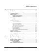
Table of Contents Chapter 1 Chapter 2 9034-OM (V4.1) Introduction . . . . . . . . . . . . . . . . . . . . . . . . . . . . . . . . . . . . . . . . . . . 1-1 Overview ................................................................................................................ 9034 Card Software Versions and this Manual ...................................................... Cobalt Reference Guides ........................................................................................
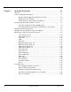
Chapter 3 Operating Instructions . . . . . . . . . . . . . . . . . . . . . . . . . . . . . . . . . . . 3-1 Overview ................................................................................................................. 3-1 Control and Display Descriptions ........................................................................... 3-1 Function Submenu/Parameter Submenu Overview .................................... 3-2 DashBoard™ User Interface .....................................................
Chapter 1 Chapter 1 Introduction Overview This manual provides installation and operating instructions for the 9034 Input Processing Analog to Digital Video Converter with Audio Embedding and Frame Sync and Dolby® Decoding Option card (also referred to herein as the 9034). Note: This manual also covers the 9034-DEC, which is the 9034 card equipped with Dolby® decoding as an option.
1 9034 Card Software Versions and this Manual 9034 Card Software Versions and this Manual When applicable, Cobalt Digital Inc. provides for continual product enhancements through software updates. As such, functions described in this manual may pertain specifically to cards loaded with a particular software build. The Software Version of your card can be checked by viewing the Card Info menu in DashBoard™. See Checking 9034 Card Information (p.
Introduction Manual Conventions Manual Conventions In this manual, display messages and connectors are shown using the exact name shown on the 9034 itself. Examples are provided below. • Card-edge display messages are shown like this: Ch01 • Connector names are shown like this: SDI OUT In this manual, the terms below are applicable as follows: • 9034 refers to the 9034 Input Processing Analog to Digital Video Converter with Audio Embedding and Frame Sync and Dolby® Decoding Option card.
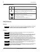
1 Safety Summary Labeling Symbol Definitions Attention, consult accompanying documents. Electronic device or assembly is susceptible to damage from an ESD event. Handle only using appropriate ESD prevention practices. If ESD wrist strap is not available, handle card only by edges and avoid contact with any connectors or components. Symbol (WEEE 2002/96/EC) For product disposal, ensure the following: • Do not dispose of this product as unsorted municipal waste. • Collect this product separately.
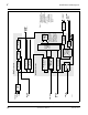
Introduction 9034 Functional Description 9034 Functional Description Figure 1-1 shows a functional block diagram of the 9034. The 9034 frame synchronizer includes a full 16-channel audio embedder that receives either 8-pair AES or 8-channel balanced analog audio inputs. The 9034 also handles AFD code insertion and transfer of Dolby® metadata. (9034-DEC only) The 9034-DEC also performs Dolby® E and Dolby® Digital™ decoding and decoded channel routing.
1-6 9034 PRODUCT MANUAL 9034BDV4 AES I/O (1-4) AN-AUD IN (1-8) AES IN (5-8) EXT REF IN (1,2) Pb IN Pr/C IN Y/Cmpst IN Video A/D [AES OUT (1-4)] S11–S14 [AES IN (1-4)] Differential Analog Audio A/D AES Decode and SRC (NOTE 2) Dolby® Decode Audio Processor Timecode Processing Metadata Extract/ Re-insert Video Processing Video Processor (NOTE 3) 2.0-to-5.1 Upmixer AES Encode Audio Embed Active: Overwrites 6 selected channels with new 5.1 mix. See text. Bypass: Bypasses 2.0-to-5.
Introduction 9034 Functional Description Video Processor Description Video Processor The 9034 provides full color processing control (luma gain and lift, chroma saturation, and color phase) of the output video. Frame Sync Function This function provides for frame sync control using either one of two external EXT REF IN (1,2) reference signals distributed with the card frame, or the input video as a frame sync reference.
1 9034 Functional Description Dolby® Metadata Extractor/Re-inserter (9034-DEC only) This function allows Dolby® metadata from the Dolby decoder, to be inserted in the output SDI. The extracted metadata is buffered and then output on a user-selectable line number on the SDI output, and on an RS-485 port on cards equipped with an appropriate Rear I/O Module. Timecode Processor (See Figure 1-2.
Introduction 9034 Functional Description Audio Processor Description The audio processor operates as an internal audio router.
1 9034 Functional Description Audio Down Mixer and Mono Mixer Function (See Figure 1-3.) The Audio Down Mixer function provides for the selection of any AES discrete, analog audio (or Dolby decoder where equipped) sources serving as Left (L), Right (R), Center (C), Left Surround (Ls), and Right Surround (Rs) individual signals to be multiplexed into a stereo pair (Down Mix Left (DM-L) and Down Mix Right (DM-R)).
Introduction 9034 Functional Description 2.0-to-5.1 Upmix Function Note: Upmix function is an optional licensable feature. This function and its controls appear only when a license key is entered and activated. (This option (identified in Cobalt® price lists as +UM) can be purchased upon initial order, or field-activated using a key string which is sent to you when this option is purchased.) The 2.0-to-5.
1 9034 Functional Description From Audio Routing/Gain AES Ch 1 – Ch 16 Control > Threshold Detect AES Ch 1 AES Ch 2 With all detected signal levels on AES Ch 3 – Ch 6 below threshold, upmixer is active and overwrites with new 5.1. AES Ch 3 AES Ch 4 AES Ch 5 AES Ch 6 - 20 dBFS - 60 dBFS L – AES Ch 1 R – AES Ch 2 L C – AES Ch 3 R LFE – AES Ch 4 (C) Ls – AES Ch 5 (LFE) Rs – AES Ch 6 (Ls) (Rs) Selected channels AES Ch 1 – Ch 6 are overwritten with the new 5.1 upmix content.
Introduction 9034 Functional Description Loudness Processor (Option +LP) Note: Loudness processor function is an optional licensable feature. This function and its controls appear only when a license key is entered and activated. (This option (identified in Cobalt® price lists as +LP) can be purchased upon initial order, or field-activated using a key string which is sent to you when this option is purchased.) If your card was purchased with option +LP, loudness processor manual supplement “5.
1 9034 Functional Description AES Audio Input Advanced Features AES Sample Rate Converter The 9034 AES inputs have sample rate converters that can be independently enabled for each AES pair to allow the card to interface with asynchronous AES sources (sources in which AES timing does not match the video input timing). The sample rate converters are set to disabled (bypassed) by default; this is necessary when embedding non-PCM AES audio such as Dolby® E or Dolby® Digital audio streams.
Introduction 9034 Functional Description Dolby® Decoding (9034-DEC only) Note: Although the 9034-DEC Dolby® decoder can provide Dolby® Digital™ (AC-3) decoding, discussion and examples here describe only Dolby® E decoding. When Dolby® E or Dolby® Digital™ is present on an embedded audio pair, the decoder produces up to 10 decoded channels (according to the Dolby® sub-format received from the metadata). All resulting channels are available as inputs to the audio router.
1 9034 Functional Description User Control Interface Figure 1-7 shows the user control interface options for the 9034. These options are individually described below. Note: All user control interfaces described here are cross-compatible and can operate together as desired. Where applicable, any control setting change made using a particular user interface is reflected on any other connected interface.
Introduction 9034 Functional Description • Note: Built-in Card Edge User Interface – Using the built-in card edge controls and display, card control settings can be set using a front panel menu. Some of the 9034 functions described in this manual are available only when using the DashBoard™, or Cobalt® OGCP-9000 or OGCP-9000/CC Remote Control Panel user interfaces.
1 9034 Functional Description 9034 Rear I/O Modules The 9034 physically interfaces to system video and audio connections using a Rear I/O Module. Figure 1-8 shows a typical 9034 Rear I/O Module. All inputs and outputs shown in the 9034 Functional Block Diagram (Figure 1-1) enter and exit the card via the card edge backplane connector. The Rear I/O Module breaks out the 9034 card edge connections to industry standard connections that interface with other components and systems in the signal chain.
Introduction Table 1-1 9034 Functional Description Supported Audio and Video Formats Item Description/Specification Input / Output Video Raster Structure: Frame Rate: 1080PsF 23.98; 24 1080p 23.98; 24 1080i (1) 25; 29.97; 30 720p 23.98; 24; 25; 29.97; 30; 50; 59.94; 60 486i (1, 2) 29.97 575i (1, 2) 25 Embedded Audio The 9034 supports all four groups (16 channels) of embedded audio at full 24-bit resolution in both SD (with extended data packets) and HD.
1 Technical Specifications Technical Specifications Table 1-2 lists the technical specifications for the 9034 Input Processing Analog to Digital Video Converter with Audio Embedding and Frame Sync card. Table 1-2 Technical Specifications Item Characteristic Note: HD specifications apply only to 9034; 9034-SD only accepts and outputs SD signals.
Introduction Table 1-2 Technical Specifications Technical Specifications — continued Item Analog Video Input (cont.) Characteristic Video Input Types: HD: Component YPbPr and RGB SMPTE SD: Composite, Component YPbPr (BetaCam™, MII™, SMPTE/N10), RGB, and Y/C Conversion Bit Depth: 12 bits SD Color Separation: 5-Line Adaptive Comb or Notch Filter Frequency Response (HD): Y: 0 – 25 MHz ± 0.3 dB Pb/B: 0 – 13.5 MHz ± 0.3 dB Pr/R: 0 – 13.5 MHz ± 0.3 dB Frequency Response (SD): 0 – 5.2 MHz ± 0.
1 Technical Specifications Table 1-2 Technical Specifications — continued Item Post-Processor Serial Digital Video Outputs (cont.) Characteristic Signal Level: 800 mV ± 10% DC Offset: 0 V ± 50 mV Jitter (HD): < 0.15 UI (all outputs) Jitter (SD): < 0.10 UI (all outputs) Overshoot: < 0.2% of amplitude AES Audio Input Standard: SMPTE 276M Number of Inputs (maximum): 8 unbalanced Input Level: 0.1 to 2.
Introduction Table 1-2 Technical Specifications Technical Specifications — continued Item AES Audio Output Characteristic Standard: SMPTE 276M Number of Outputs (maximum): 8 unbalanced Output Impedance: 75 Ω Return Loss: > 30 dB 100 kHz to 6 MHz Sample Rate: 48 kHz RS-485 Metadata I/O Metadata extracted from input video (per SMPTE 2020-1-2008) or Dolby® decoder (where equipped) on RS-485 interface; 3-wire balanced via Phoenix terminal block connector.
1 Warranty and Service Information Warranty and Service Information Cobalt Digital Inc. Limited Warranty This product is warranted to be free from defects in material and workmanship for a period of five (5) years from the date of shipment to the original purchaser, except that 4000, 5000, 6000, 8000 series power supplies, and Dolby® modules (where applicable) are warranted to be free from defects in material and workmanship for a period of one (1) year. Cobalt Digital Inc.
Introduction Contact Cobalt Digital Inc. Contact Cobalt Digital Inc. Feel free to contact our thorough and professional support representatives for any of the following: 9034-OM (V4.1) • Name and address of your local dealer • Product information and pricing • Technical support • Upcoming trade show information Phone: (217) 344-1243 Fax: (217) 344-1245 Web: www.cobaltdigital.com General Information: info@cobaltdigital.com Technical Support: support@cobaltdigital.
This page intentionally blank 1-26 9034 PRODUCT MANUAL 9034-OM (V4.
Chapter 2 Chapter 2 Installation and Setup Overview This chapter contains the following information: • Setting I/O Switches for AES I/O (1-4) Ports (p. 2-1) • Installing the 9034 Into a Frame Slot (p. 2-2) • Installing a Rear I/O Module (p. 2-5) • Setting Up 9034 Network Remote Control (p.
2 Installing the 9034 Into a Frame Slot Rear of Card AES I/O 4 AES I/O 3 AES I/O 2 AES I/O 1 S11 S12 S13 S14 INPUT MODE (Factory Default) OUTPUT MODE • • • • Figure 2-1 9034 AES I/O (1-4) Mode Switches Installing the 9034 Into a Frame Slot CAUTION Heat and power distribution requirements within a frame may dictate specific slot placement of cards.
Installation and Setup Note: Installing the 9034 Into a Frame Slot • If installing the 9034 in an 8310-C-BNC or 8310-BNC frame (which is pre-equipped with a 100-BNC rear I/O module installed across the entire backplane) or a slot already equipped with a suitable I/O module, proceed to card installation steps below. • If installing the 9034 in a slot with no rear I/O module, a Rear I/O Module is required before cabling can be connected. Refer to Installing a Rear I/O Module (p.
2 Installing the 9034 Into a Frame Slot 9. Note: The 9034 BNC inputs are internally 75-ohm terminated. It is not necessary to terminate unused BNC inputs or outputs. Note: External frame sync reference signals are received by the card over a reference bus on the card frame, and not on any card rear I/O module connectors. The frame has BNC connectors labeled REF 1 and REF 2 which receive the reference signal from an external source such as a house distribution.
Installation and Setup Installing a Rear I/O Module Installing a Rear I/O Module Note: This procedure is applicable only if a Rear I/O Module is not currently installed in the slot where the 9034 is to be installed. If installing the 9034 in a 8310-C-BNC or 8310-BNC frame (which is pre-equipped with a 100-BNC rear I/O module installed across the entire backplane) or a slot already equipped with a suitable I/O module, omit this procedure.
2 Installing a Rear I/O Module 9034 Rear I/O Modules Table 2-1 shows and describes the full assortment of Rear I/O Modules specifically for use with the 9034. Notes: • Rear I/O Modules equipped with 3-wire Phoenix connectors are supplied with removable screw terminal block adapters. For clarity, the adapters are omitted in the drawings below.
Installation and Setup Table 2-1 Installing a Rear I/O Module 9034 Rear I/O Modules — continued 9034 Rear I/O Module RM20-9034-C Description Provides the following connections: • Analog Y/composite, Pr/C, and Pb coaxial inputs (Y/Cmpst, Pr/C, and Pb, respectively) • Four AES I/O coaxial input/outputs (AES I/O 1 thru AES I/O 4; I/O function of each connection is user-configurable) • Two dedicated AES coaxial audio inputs (AES IN 5 and AES IN 6) • Eight analog balanced audio inputs (AN-AUD IN 1 thru AN-AU
2 Installing a Rear I/O Module Table 2-1 9034 Rear I/O Modules — continued 9034 Rear I/O Module RM20-9034-F Description Provides the following connections: • Analog Y/composite, Pr/C, and Pb coaxial inputs (Y/Cmpst, Pr/C, and Pb, respectively) • Eight analog balanced audio inputs (AN-AUD IN 1 thru AN-AUD IN 8) • Four AES I/O coaxial input/outputs (AES I/O 1 thru AES I/O 4; I/O function of each connection is user-configurable) • Two buffered SDI coaxial outputs (SDI OUT) • Dolby® RS-485 metadata output
Installation and Setup Setting Up 9034 Network Remote Control Setting Up 9034 Network Remote Control Perform remote control setup in accordance with Cobalt® reference guide “Remote Control User Guide” (PN 9000RCS-RM).
This page intentionally blank 2-10 9034 PRODUCT MANUAL 9034-OM (V4.
Chapter 3 Chapter 3 Operating Instructions Overview This chapter contains the following information: If you are already familiar with using DashBoard or a Cobalt Remote Control Panel to control Cobalt cards, please skip to 9034 Function Submenu List and Descriptions (p. 3-9). • Control and Display Descriptions (p. 3-1) • Accessing the 9034 Card via Remote Control (p. 3-5) • Checking 9034 Card Information (p. 3-7) • Ancillary Data Line Number Locations and Ranges (p.
3 Control and Display Descriptions Note: When a setting is changed, settings displayed on DashBoard™ (or a Remote Control Panel) are the settings as effected by the 9034 card itself and reported back to the remote control; the value displayed at any time is the actual value as set on the card. Function Submenu/Parameter Submenu Overview The functions and related parameters available on the 9034 card are organized into function submenus, which consist of parameter groups as shown below.
Operating Instructions Control and Display Descriptions DashBoard™ User Interface (See Figure 3-2.) The 9034 function submenus are organized in DashBoard™ using tabs. When a tab is selected, each parametric control or selection list item associated with the function is displayed. Scalar (numeric) parametric values can then be adjusted as desired using the GUI slider controls. Items in a list can then be selected using GUI drop-down lists.
3 Control and Display Descriptions Cobalt® Remote Control Panel User Interfaces (See Figure 3-3.) Similar to the function submenu tabs using DashBoard™, the Remote Control Panels have a Select Submenu key that is used to display a list of function submenus. From this list, a control knob on the Control Panel is used to select a function from the list of displayed function submenu items.
Operating Instructions Accessing the 9034 Card via Remote Control Accessing the 9034 Card via Remote Control Access the 9034 card using DashBoard™ or Cobalt® Remote Control Panel as described below. Accessing the 9034 Card Using DashBoard™ 1. On the computer connected to the frame LAN, open DashBoard™. 2. As shown below, in the left side Basic View Tree locate the Network Controller Card associated with the frame containing the 9034 card to be accessed (in this example, “MFC-8320-N SN: 00108053”).
3 Accessing the 9034 Card via Remote Control Card Access/Navigation Tree Pane Card Info Pane Card Function Submenu and Controls Pane 9034_ DB_ACCESS3A3.PNG Accessing the 9034 Card Using a Cobalt® Remote Control Panel Press the Select Device key and select a card as shown in the example below. 9034_3366_3392.JPG This display shows the list order number of the device that is ready for selection This display shows the devices assigned to the Control Panel.
Operating Instructions Checking 9034 Card Information Checking 9034 Card Information The operating status and software version the 9034 card can be checked using DashBoard™ or the card edge control user interface. Figure 3-4 shows and describes the 9034 card information screen using DashBoard™ and accessing card information using the card edge control user interface. Note: Proper operating status in DashBoard™ is denoted by green icons for the status indicators shown in Figure 3-4.
3 Ancillary Data Line Number Locations and Ranges Ancillary Data Line Number Locations and Ranges Table 3-1 lists typical default output video VANC line number locations for various ancillary data items that may be passed or handled by the card. Table 3-1 Typical Ancillary Data Line Number Locations/Ranges Default Line No.
Operating Instructions 9034 Function Submenu List and Descriptions 9034 Function Submenu List and Descriptions Table 3-2 individually lists and describes each 9034 function submenu (‘tab”) and its related list selections, controls, and parameters. Where helpful, examples showing usage of a function are also provided. Table 3-2 is primarily based upon using DashBoard™ to access each function and its corresponding submenus and parameters.
3 9034 Function Submenu List and Descriptions Table 3-2 9034 Function Submenu List Sets the 9034 video signal input type and preference and priority. Video Signal Controls • HD Analog Input Type When receiving analog video input, sets the 9034 HD input video type to accept received input signal from choices shown. Note: Input type must be appropriately set for the 9034 to correctly process the received input.
Operating Instructions Table 3-2 9034 Function Submenu List and Descriptions 9034 Function Submenu List — continued Audio Input Controls Controls the AES Audio Input features for the eight AES pairs, and displays signal status for received AES pairs. Also provides global unity routing/parameter control resets. Note: Also refer to AES Audio Input Advanced Features (p. 1-14) in Chapter 1, “Introduction” for detailed information regarding these functions.
3 Table 3-2 9034 Function Submenu List and Descriptions 9034 Function Submenu List — continued (continued) • Status Displays Individual signal status displays for AES pairs 1-8 as follows: • Not Present: Indicates AES pair does not contain recognized audio PCM data. Note: Channel displaying Not Present may still carry usable audio data with Not Present being displayed due to invalid headers. • • • • Present, Professional: Indicates AES pair contains recognized AES audio PCM data.
Operating Instructions Table 3-2 9034 Function Submenu List and Descriptions 9034 Function Submenu List — continued (continued) • Apply Audio Channel Selection Applies embedded and AES unity channel selection (as set in the above drop-down lists). To apply the selections, click the Confirm button. When Confirm is clicked, a Confirm? pop-up appears, requesting confirmation. • Click Yes to proceed with the unity reset. • Click No to reject unity reset.
3 Table 3-2 9034 Function Submenu List and Descriptions 9034 Function Submenu List — continued Provides the following Video Proc parametric controls. • Video Proc Video Proc (On/Off) provides master on/off control of all Video Proc functions. • When set to Off, all processing is bypassed. • When set to On, currently displayed parameter settings take effect. • Reset to Unity Reset to Unity provides unity reset control of all Video Proc functions.
Operating Instructions Table 3-2 9034 Function Submenu List and Descriptions 9034 Function Submenu List — continued Allows assignment of AFD (Active Format Description) codes to the SDI output video. AFD Note: This function only marks the SDI output with an AFD code. Actual AFD processing must be performed by a downstream card or system that recognizes an AFD code assigned here. • Output Mode Drop-down selection determines action to take in presence or absence of existing AFD code on input video.
3 9034 Function Submenu List and Descriptions Table 3-2 9034 Function Submenu List — continued Provides video Frame Sync delay control and audio re-sync tools. Framesync • Framesync Enable Disables the Frame Sync function, or selects from choices below. • Off: Video path bypasses frame sync entirely; output video timing tracks with input video timing. • Reference 1: Allows Frame Sync function to use external Reference 1 as the reference (“house”) standard.
Operating Instructions Table 3-2 9034 Function Submenu List and Descriptions 9034 Function Submenu List — continued (continued) • Input Video Mode Fixed Delay Control When Framesync is enabled and set to Input Video, allows adding video delay. This is useful when compensating for processes which result in large audio delays. (Range is 0.0000 thru 300.0 msec.) • Framesync Audio SRC On/Off Control When Framesync is enabled and set to Input Video, allows disabling audio SRC.
3 9034 Function Submenu List and Descriptions Table 3-2 9034 Function Submenu List — continued (continued) • Audio Hard Resync Threshold Control Sets threshold at which hard resync is applied if audio-video offset exceeds threshold (see below). Hard resync provides fastest snyc-up suitable for off-air manipulation. Conversely, a threshold setting high enough to accommodate normal on-air offsets allows on-air resync that is glitch-free. (Range is 1.5 to 13.0 frames in 0.
Operating Instructions Table 3-2 9034 Function Submenu List and Descriptions 9034 Function Submenu List — continued (continued) • Current Audio Delay Display Displays the current input-to-output audio delay (in msec units) as well as in terms of Frames/fractional frame (in number of lines). • Video Delay Display Displays the current input-to-output video delay (in msec units) as well as in terms of Frames/fractional frame (in number of lines).
3 9034 Function Submenu List and Descriptions Table 3-2 9034 Function Submenu List — continued (continued) • Custom Color Hue Adjusts raster hue (phase angle) for custom LOS color. (-360° to 360° range in 0.1° steps; null = 0°) • Custom Color Saturation Adjusts raster saturation level for custom LOS color. (0% to 100% range in 0.1% steps) • Custom Color Y Level Adjusts raster luma level for custom LOS color.
Operating Instructions Table 3-2 9034 Function Submenu List and Descriptions 9034 Function Submenu List — continued Embedded Audio Group 1/2 The example above shows various Source selections and individual audio control settings for various audio sources fed to the Destination channels Embedded Ch 1 thru Embedded Ch 8 in Embedded Audio Groups 1 and 2, with the resulting setup (right).
3 9034 Function Submenu List and Descriptions Table 3-2 9034 Function Submenu List — continued (continued) • SD Audio Depth Allows option of using 24-bit audio data structure per SMPTE 272M, §3.10 (default is 20-bit per SMPTE 272M, §3.5). Note: • If 24-bit depth is desired, make certain downstream equipment is compatible with 24-bit SD audio data. • Depth control setting applied here affects both Embedded Audio Group 1/2 and 3/4.
Operating Instructions Table 3-2 9034 Function Submenu List and Descriptions 9034 Function Submenu List — continued (continued) • Down Mix Left or Right as Source Down Mix Left and Down Mix Right selections in Source drop-down list allow either downmixer left or right channel to be the source for the selected destination Embedded Audio Group channel.
3 Table 3-2 9034 Function Submenu List and Descriptions 9034 Function Submenu List — continued (continued) • Audio LTC as Source LTC selection in Source drop-down list allows any timecode format received by the card to be outputted as audio LTC over an embedded audio output (destination) channel. (In this example, audio LTC is the source for destination Embedded Ch 1) Note: • When LTC is selected as source, Gain and Mute controls are disabled.
Operating Instructions Table 3-2 9034 Function Submenu List and Descriptions 9034 Function Submenu List — continued Embedded Audio Group 3/4 • SD Audio Depth Selects the audio source for each embedded audio channel 9 thru 16 (Embedded Audio Groups 3 and 4). Also provides Gain, Phase Invert, and Muting controls for each channel. Allows option of using 24-bit audio data structure per SMPTE 272M, §3.10 (default is 20-bit per SMPTE 272M, §3.5).
3 9034 Function Submenu List and Descriptions Table 3-2 9034 Function Submenu List — continued AES Audio Out Pairs 1-4 Routes audio sources to discrete AES output channels 1 thru 8 (AES Audio Out Pairs 1-4). Also provides Gain, Phase Invert, and Muting controls for each channel.
Operating Instructions Table 3-2 9034 Function Submenu List and Descriptions 9034 Function Submenu List — continued (continued) Note: • AES Ch 2 thru AES Ch 8 have controls that are identical to the Source, Gain, Mute, and Phase controls described here for AES Ch 1. Therefore, only the AES Ch 1 controls are shown here. • For each channel, its source and destination should be considered and appropriately set. Unused destination channels should be set to the Silence selection.
3 Table 3-2 9034 Function Submenu List and Descriptions 9034 Function Submenu List — continued (continued) • Dolby® Decoded Channel as Source (9034-DEC only) Dolby Ch 1 thru Dolby Ch 8 range in Source drop-down list enables a Dolby® decoded channel to be the source for the selected destination AES channel. (In this example, Dolby® decoded Ch 1 is the source for destination AES Ch 1) • • • Note: Drop-down choices of Ch 1 thru Ch 8 and Mix 1/Mix 2 represent maximum channels available.
Operating Instructions Table 3-2 9034 Function Submenu List and Descriptions 9034 Function Submenu List — continued (continued) • Gain (dB) Control Adjusts and displays relative gain (in dB) applied to the corresponding destination AES channel. (-80 to +40 dB range in 0.1 dB steps; unity = 0.0 dB) • Mute Control Allows pushbutton On/Off channel muting while saving all other settings.
3 9034 Function Submenu List and Descriptions Table 3-2 9034 Function Submenu List — continued AES Audio Out Pairs 5-8 Routes audio sources to AES output channels 9 thru 16 (AES Audio Out Pairs 5-8). Also provides Gain, Muting, and Phase Invert controls for each channel. Note: • AES Ch 9 thru AES Ch 16 have controls that are identical to the Source, Gain, Mute, and Phase controls described for AES Ch 1. Refer to AES Audio Out Pairs 1-4 on page 3-26 for descriptions of these controls.
Operating Instructions Table 3-2 9034 Function Submenu List and Descriptions 9034 Function Submenu List — continued (9034-DEC only) Routes a Dolby® encoded pair to the Dolby® decoder, and provides Dolby® configuration display and metadata handling controls. Dolby Decoder Note: • The Dolby tab controls described here appear only on card equipped with Dolby Decoder option (-DEC). • Decoded channels shown in DashBoard™ correlate to typical channel designations as shown below.
3 Table 3-2 9034 Function Submenu List and Descriptions 9034 Function Submenu List — continued (continued) • Dolby® Mode Display Shows specific bitstream information and Dolby® decoding type (Dolby® E or Dolby® Digital) for input applied to Dolby® decoder. (In this example, Dolby® E 20-bit with 5.1+2 decoded channel configuration is being decoded) If selected input has invalid or missing Dolby® data (such as if wrong channels are applied to decoder), is displayed.
Operating Instructions Table 3-2 9034 Function Submenu List and Descriptions 9034 Function Submenu List — continued (continued) • Metadata Output Line Allows selection of SMPTE 2020-1 metadata line location within the VANC space for source embedding selected above. (Range is 9 thru 41; default is line #13.
3 9034 Function Submenu List and Descriptions Table 3-2 9034 Function Submenu List — continued (9034-DEC only) Displays the status and programming details for each Dolby® E AC-3 program dictated by the received external metadata. Dolby E Metadata Note: • This display is read-only. No changes can be made to the settings. All displays are reports per the received metadata. • Information provided here is intended as an overview of the screen. Displayed parameters are per ATSC A/52B definitions.
Operating Instructions Table 3-2 9034 Function Submenu List and Descriptions 9034 Function Submenu List — continued (9034-DEC only) Displays the status and programming details for Dolby® Digital program dictated by the received external metadata. Dolby D Metadata Note: • This display is read-only. No changes can be made to the settings. All displays are reports per the received metadata. • Information provided here is intended as an overview of the screen.
3 9034 Function Submenu List and Descriptions Table 3-2 9034 Function Submenu List — continued Provides timecode data extraction from various sources, and provides formatting and re-insertion controls for inserting the timecode into the output video. Timecode Shown below is an example in which received video with VITC waveform timecode is to be converted to SDI ATC_VITC timecode data. Each Timecode control is fully described on the pages that follow.
Operating Instructions Table 3-2 9034 Function Submenu List and Descriptions 9034 Function Submenu List — continued (continued) Audio LTC and RS-485 LTC controls described below only appear on cards with +LTC licensed optional feature. This feature allows bidirectional conversion between VBI-based timecode and LTC timecode on audio and RS-485 interfaces. • Timecode Source Status Displays Displays the current status and contents of the supported timecode formats shown to the left.
3 9034 Function Submenu List and Descriptions Table 3-2 9034 Function Submenu List — continued (continued) • Output Status Display Displays the current content and source being used for the timecode data as follows: • Output status OK (in this example, running analog VITC timecode received and outputted). • Timecode not available due to lack of appropriate input timecode data on enabled formats.
Operating Instructions Table 3-2 9034 Function Submenu List and Descriptions 9034 Function Submenu List — continued (continued) • HD ATC_LTC Insertion Control For HD output, enables or disables ATC_LTC timecode insertion into the output video, and selects the line number for ATC_LTC timecode data. • HD ATC_VITC Insertion Control For HD output, enables or disables ATC_VITC timecode insertion into the output video, and selects the line number for ATC_VITC1 and ATC_VITC2.
3 9034 Function Submenu List and Descriptions Table 3-2 9034 Function Submenu List — continued Audio Mixing Provides down-mix audio routing selections that multiplexes any five AES, analog audio, or Dolby decoder (where equipped) channel sources into a stereo pair (Down Mix Left and Down Mix Right), or selection of any two audio sources to be mono-mixed to serve as a monaural source.
Operating Instructions Table 3-2 9034 Function Submenu List and Descriptions 9034 Function Submenu List — continued (continued) • Surround Mix Ratio Control Adjusts the attenuation ratio of surround-channel content from 5-channel source that is re-applied as Lo and Ro content to the DM-L and DM-R stereo mix. • Minimum attenuation setting (-0.0 dB) applies no ratiometric reduction. Surround-channel content is restored with no attenuation, making Lo and Ro content more predominate in the overall mix.
3 9034 Function Submenu List and Descriptions Table 3-2 9034 Function Submenu List — continued (continued) Note: • 2.0-to-5.1 upmixer function is an optional licensable feature. This function and its controls appear only when a license key is entered and activated. Refer to Licensable Features function description on page 3-45 for more information. • Channel sources used by the upmixer are post-processed signals received from the Audio Routing/Gain Control function.
Operating Instructions Table 3-2 9034 Function Submenu List and Descriptions 9034 Function Submenu List — continued (continued) • Up Mixer Mode Control Enables or bypasses upmixer as follows: • Auto: Automatic enable/bypass of 5.1 upmix function as follows: • If detected signal level on all four of the selected channels designated as Center, LFE, Left Surround, and Right Surround are below the level threshold set using the 5.
3 Table 3-2 9034 Function Submenu List and Descriptions 9034 Function Submenu List — continued (continued) • 5.1 Detection Threshold Control Adjusts the threshold at which selected channels designated as C, LFE, Ls, and Rs are considered to have viable content, or at which signal levels can be considered insignificant when upmixer enable is set to Auto. Setting affects automatic enable/bypass of 5.
Operating Instructions Table 3-2 9034 Function Submenu List and Descriptions 9034 Function Submenu List — continued Sets the test tone frequency for each of four tone generators (Tone Generator 1 thru 4). Tone Generator • Frequency Selection Lists • • • Selects the frequency for each of the four tone generators. 18 discrete sine wave frequencies are available, ranging from 50 Hz to 16 kHz (default frequency is 1.0 kHz). Note: Unity-gain signal level is equivalent to -20 dBu.
3 9034 Function Submenu List and Descriptions Table 3-2 9034 Function Submenu List — continued Allows up to 16 card user settings configuration presets to be saved in a Preset and then recalled (loaded) as desired. All current settings (including list selections and scalar (numeric) control settings such as Gain, etc.) are saved when a Preset Save is invoked.
Operating Instructions Table 3-2 9034 Function Submenu List and Descriptions 9034 Function Submenu List — continued (continued) • Preset Name With one of 16 presets selected, provides for entry of custom name for the preset (as shown in example below). Entering text in Preset Name field (in this example, “RCVR21”) applies custom name to selected Preset (in this example, Preset 2) Note: • Preset name can be seven ASCII characters maximum.
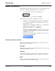
3 Troubleshooting Troubleshooting This section provides general troubleshooting information and specific symptom/corrective action for the 9034 card and its remote control interface. The 9034 card requires no periodic maintenance in its normal operation; if any error indication (as described in this section) occurs, use this section to correct the condition.
Operating Instructions Troubleshooting 9034 Card Edge Status/Error Indicators and Display Figure 3-6 shows and describes the 9034 card edge status indicators and display. These indicators and the display show status and error conditions relating to the card itself and remote (network) communications (where applicable).
3 Troubleshooting DashBoard™ Status/Error Indicators and Displays Figure 3-7 shows and describes the DashBoard™ status indicators and displays. These indicator icons and displays show status and error conditions relating to the 9034 card itself and remote (network) communications.
Operating Instructions Troubleshooting Access Card Info panes for specific cards by clicking the card slot position in the Card Access/Navigation Tree pane (as shown in the example in Figure 3-8). Status for selected card is shown here (in this example, connection OK and “Fan Door Open” alert) By clicking on “Slot 0: MFC-8320-N” in this example, Card Info is displayed for frame Network Controller Card Card general information is displayed in lower portion of Card Info pane 9034_TS_CARD_INFO_ACCESS_A.
3 Troubleshooting Basic Troubleshooting Checks Failures of a general nature (affecting many cards and/or functions simultaneously), or gross inoperability errors are best addressed first by performing basic checks before proceeding further. Table 3-3 provides basic system checks that typically locate the source of most general problems. If required and applicable, perform further troubleshooting in accordance with the other troubleshooting tables in this section.
Operating Instructions Troubleshooting 9034 Processing Error Troubleshooting Table 3-4 provides 9034 processing troubleshooting information. If the 9034 card exhibits any of the symptoms listed in Table 3-4, follow the troubleshooting instructions provided. In the majority of cases, most errors are caused by simple errors where the 9034 is not appropriately set for the type of signal being received by the card.
3 Troubleshooting Table 3-4 Troubleshooting Processing Errors by Symptom — continued Symptom DashBoard™ shows Framesync Status error message in 9034 Framesync function submenu screen. Error/Condition Specified Minimum Latency Frames setting exceeds 9034 card buffer space for the selected output video format Corrective Action Reduce the Minimum Latency Frames setting as specified in the error message to correct the error.
Operating Instructions Table 3-4 Troubleshooting Troubleshooting Processing Errors by Symptom — continued Symptom Audio signal(s) do not route as expected. Parameter control not available as expected.
3 Troubleshooting Table 3-4 Troubleshooting Processing Errors by Symptom — continued Symptom Audio not processed or passed through card (cont.). Error/Condition Corrective Action • Upmixer inadvertently enabled (Upmixer Licensed Feature only) • Make certain upmixer is set to Bypass if not intended for use.
Cobalt Digital Inc. 2406 E. University Ave. Urbana, IL 61802 Voice 217.344.1243 • Fax 217.344.1245 www.cobaltdigital.com 9034-OM (V4.