
Manual

Configuration Dip Switch Settings
The 9018 has four 4 segment dip switches mounted on the forward edge of the PCB (Fig 4.); one for each
converter. These configuration switches provide the capability to set the 9018 converter to display a color bar
test pattern, turn setup on or off, and turn the chroma on or off. The switches work identically for each converter
and function as follows (Fig. 5).
Output Analog Video Gain Adjustment
To adjust the output amplitude of the analog composite output, use the potentiometers located on the front of the
card next to the 4 position configuration switches (Fig. 4). Each converter has one adjustment potentiometer
labeled "A" for the "A" converter, "B " for the "B" converter, etc. Turning the adjustment clockwise increases the
output amplitude, while counter-clockwise rotation reduces the output amplitude.
9018 Owner's Manual
Copyright 2001-2007 Cobalt Digital Inc.
Page 3 of 4
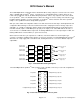
Fig. 4: Configuration Switches and Output Gain Control
RP101
A-Gain
A-Cnfg S101
1 2 3 4
A-Lock
RP201
B-Gain
B-Cnfg S201
1 2 3 4
B-Lock
RP301
C-Gain
C-Cnfg S301
1 2 3 4
C-Lock
RP401
D-Gain
D-Cnfg S401
1 2 3 4
D-Lock
Note: ON is defined as the "UP" position furthest away from the board.
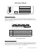
Segment Function
1
2
3
4
Color Bar Test Pattern: ON (up) (requires valid SDI input)
VBI Enable: ON at all times regardless of Switch setting
Setup: ON (up) or OFF (valid when in NTSC only)
Color Enable: ON - turns Chroma on, OFF = Chroma off
Fig. 5: Configuration Settings
Fig. 3: 9018 Switch and Potentiometer Locations
LED A
Locked
S101 A-Configuration
RP101
A-Gain
S201 B-Configuration
RP201
B-Gain
LED C
Locked
S301 D-Configuration
RP301
C-Gain
S401 D-Configuration
RP401
D-Gain
LED B
Locked
LED D
Locked
A Channel Deserialize, encode and DA
B Channel Deserialize, encode and DA
C Channel Deserialize, encode and DA
D Channel Deserialize, encode and DA
Power
Supply