
Manual


The Cobalt Digital 9016 is a high performance Triple 4:2:2 SDI digital to analog composite converter card.
The card is 100% compatible with openGear
TM
frames. Through the use of the DashBoard Lite software, which
can be found at the openGear
TM
website, the 9016 will report parameter status to any computer on the same
network as the openGear
TM
frame. The DashBoard Lite software also allows for remote resetting of the video
lines and hardware firmware upgrades. For more information on openGear
TM
frames and other cards in the
openGear
TM
family see the openGear
TM
website at http://www.opengear.tv.
Gain, status LED and configuration switches are all mounted on the board edge to allow adjustments and
configuration without having to remove the board from the frame. Output gain control for analog composite is
adjustable +5 / -10 IRE. Configuration switches allow for Setup On/Off (NTSC Only); Color On/Off; VBI
Blanking and Test Color Bars On/Off (requires a 270-Mbit input to clock bars). A status LED per converter,
indicates a digital input lock by solid on indication. The Status LED flashes on/off when input digital stream is
lost. A dark, non-flashing status LED indicates power loss.
Outputs can be user configured to be analog composite or reclocked SDI.
Other features include true sync output levels of -300 mV, on board resettable fuses and low power (per
converter) consumption enabling a large number of conversions per frame.
9016 Owner's Manual
Page 2 of 4
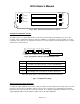
Fig. 2: Rear view of Frame BNC connector panel
.
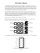
Fig. 1: 9016 Triple SDI to Analog Composite
Equalize
& Reclock
Serial to
Parallel
Digital to
Analog
Encoder
DA
Analog Composite
or SDI Output
4:2:2 SDI Input
SMPTE 259M
DA
SW
SW
Equalize
& Reclock
Serial to
Parallel
Digital to
Analog
Encoder
DA
Analog Composite
or SDI Output
4:2:2 SDI Input
SMPTE 259M
DA
SW
SW
Equalize
& Reclock
Serial to
Parallel
Digital to
Analog
Encoder
DA
Analog Composite
or SDI Output
4:2:2 SDI Input
SMPTE 259M
DA
SW
SW
SW
The Cobalt Digital 8310 openGear
TM
frame provides a total of 10 BNC connectors per card. I/O configuration is
shown in Fig 2.
2
4
6
1
3
5
87
B Out 1
A input SDI
A Out 2
B Input SDI
B Out 2
A Out 1
A Out 3
C Out 1
9 10 C Out 2C Input SDI