Cobalt Digital Inc. 9011 Standard Definition Digital to Analog Converter 10-bit SDI to Analog Composite, Y/C, RGB and Component Owner’s Manual 9011-OM Version: 1.
9011 • Standard Definition D/A 10-bit SDI to Analog Composite, Y/C, RGB and Component Owner’s Manual • • • • • Cobalt Part Number: 9011-OM Document Version: 1.1 Printed in the United States. Last Author: CGG Printing Date: 1/4/2013 The information contained in this Owner’s Manual is subject to change without notice or obligation. Copyright © 2013 Cobalt Digital Inc. All rights reserved. Contents of this publication may not be reproduced in any form without the written permission of Cobalt Digital Inc.
Important Regulatory and Safety Notices Before using this product and any associated equipment, refer to the “Important Safety Instructions” listed below so as to avoid personnel injury and to prevent product damage. Products may require specific equipment, and /or installation procedures be carried out to satisfy certain regulatory compliance requirements. Notices have been included in this publication to call attention to these specific requirements.
Environmental Information The equipment that you purchased required the extraction and use of natural resources for its production. It may contain hazardous substances that could impact health and the environment. To avoid the potential release of those substances into the environment and to diminish the need for the extraction of natural resources, Cobalt Digital encourages you to use the appropriate take-back systems.
Contents Introduction 6 In This Chapter .......................................................................................................................... 6 A Word of Thanks ..................................................................................................................... 6 Overview.................................................................................................................................... 6 Features.........................................................
Introduction In This Chapter This chapter includes the following sections: • A Word of Thanks • Overview • Functional Block Diagram • Supported Video Formats • Documentation Terms A Word of Thanks Congratulations on choosing the openGearTM 9011 Standard Definition D/A 10-bit SDI to Analog Composite, Y/C, RGB and Component. The 9011 is part of a full line of modular conversion gear for broadcast TV environments.
extended filtering, DNR and Gamma configuration. All adjustments can be saved to non-volatile memory or Factory defaults can be restored. A De-jitter VCXO is included to reduce input jitter from high frequencies down to 2Hz. The 9011 has four reclocked digital output copies of the input SDI signal or three when the Genlock input is used, and one BNC reserved for Black Burst input. The user must adjust the SDI source’s HPhase for horizontal sync alignment.
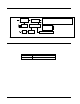
Functional Block Diagram This section diagrams the basic signal flow of your 9011 product. SDI Input SDI Output Frame Ref or BNC 2 Ref SDI Input Processing De-jitter SDI DA Microprocessor SW Ref GL 10 bit Encoding,Dig. Proc., Gamma Cntl., DNR, Filtering, 8:8:8 or 16:16:16 Output Filter, Mux Output Amps Config & Proc SW Analog Outputs Config. as: 4 Composite 2 Composite & Y/C 2 Y/C 1 Composite & Component 9011 Block Diagram Figure 1.
Documentation Terms The following terms are used throughout this guide: • “Frame” refers to the HPF-9000 or 8321 20-slot frame that houses the 9011 card. • “Operator” and “User” both refer to the person who uses the 9011. • “Board” and “Card” all refer to the 9011 card itself, including all components and switches. • “System” and “Video system” refers to the mix of interconnected production and terminal equipment in which the 9011 operates. 9011 Owner’s Manual • (V 1.
Installation and Setup In This Chapter This chapter includes the following sections: • Static Discharge • Unpacking • Rear Module Installation (Optional) • Board Installation • BNC Connections • Menu Structure • Factory Defaults Static Discharge Whenever handling the card and other related equipment, please observe all static discharge precautions as described in the following note: Static discharge can cause serious damage to sensitive semiconductor devices.
Rear Module Installation (Optional) If you are installing the card in a 8310-C-BNC or 8310-BNC frame (one with a 100 BNC rear module installed across the entire back plane), skip this section. If you are installing the card into a slot with no rear module, you should have ordered and received an appropriate 9011 rear module. You will need to install it in your frame before you can connect cables. Use the following steps to install a rear module in a frame: 1.
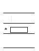
Rear Modules Available for 9011 This section provides instructions for connecting cables to 9011 rear modules. Connect the input and output cables according to the appropriate following diagram. Split rear module RM20-9011-A/S allow two cards to be installed in adjacent slots. RM20-9011-A RM20-9011-A/S Figure 3. BNC Designations for the Card Rear Module available for the 9011. 9011 Owner’s Manual • (V 1.
Board Installation Use the following steps to install the card in the frame: 1. Warning Refer to the frame product manual to ensure that the frame is properly installed according to instructions. Heat and power distribution requirements within a frame may dictate specific slot placement of cards. Cards with many heat-producing components should be arranged to avoid areas of excess heat build-up, particularly in frames using convection cooling. 2.
Card Control and Status Card Control Switches The majority of the card control can be performed by the 8 switches on switch bank S1. Their operation is detailed in the following table. S1.1 ON* ON ON OFF OFF OFF OFF S1.4 ON* OFF S1.5 ON OFF* S1.6 ON* OFF S1.7 ON* OFF S1.8 ON* OFF S1.2 ON* OFF OFF ON ON OFF OFF S1.
Card Status LEDs The card LEDs report the lock status of the device. See the table below for an explanation of each function. LED NAME LOCK LED NTSC LED PAL LED RMT LED DESCRIPTION Flashes green when not locked to input signal. When locked illuminates steady green. When S3 or S4 not at 0, indicates state of parameter.
Remote Control In This Chapter This section provides a detailed explanation on using remote control functions with your card. DashBoard Control System Software The DashBoard Control System enables you to monitor and control openGearTM frames and controller cards from a computer. The DashBoard software and manual can be downloaded from the Cobalt Digital Inc. website (www.cobaltdigital.com).
Technical Specifications Table 4. Card - Technical Specifications Category Parameter Serial Digital Video Input Analog Video Output Reference Video Input Other Specification Data Rates Supported SMPTE 259M-C SD-SDI: 270 Mbps Frame Rates Supported 486i 29.
Service Information In This Chapter This chapter includes the following sections: • Troubleshooting Checklist • Warranty and Repair Policy Troubleshooting Checklist Routine maintenance to this openGearTM product is not required. In the event of problems with your card, the following basic troubleshooting checklist may help identify the source of the problem.
Warranty and Repair Policy Cobalt Digital Inc. Limited Warranty This product is warranted to be free from defects in material and workmanship for a period of five (5) years from the date of shipment to the original purchaser, except that 4000, 5000, 6000, 8000 series power supplies, and Dolby® modules (where applicable) are warranted to be free from defects in material and workmanship for a period of one (1) year. Cobalt Digital Inc.
In Case of Problems Should any problem arise with your openGear® card, please contact the Cobalt Digital Inc. Technical Support Department. (Contact information is supplied at the end of this publication.) A Return Material Authorization number (RMA) will be issued to you, as well as specific shipping instructions, should you wish our factory to repair your openGear® card. If required, a temporary replacement module will be made available at a nominal charge.
Ordering Information 9011 and Related Products Your 9011 Standard Definition D/A 10-bit SDI to Analog Composite, Y/C, RGB and Component is a part of the openGearTM family of products. Cobalt Digital offers a full line of openGearTM terminal equipment including distribution, conversion, monitoring, synchronizers, encoders, decoders, embedders, and de-embedders, as well as analog audio and video products.
Contact Us Contact Cobalt Digital Inc. PHONE E-MAIL POSTAL SERVICE General Business Office and Technical Support 217.344.1243 Fax 217.344.1245 General Information Info@cobaltdigital.com Sales Information Sales@cobaltdigital.com Cobalt Digital Inc. 2406 East University Avenue Urbana, IL 61802 USA Visit us at the Cobalt Digital Inc. website. http://www.cobaltdigital.