
User manual

Page 30 8321 User Manual •
••
• (V 1.1)
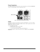
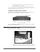
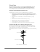
DIP Switches on the MFC-8320-N
The following DIP Switches are located on the MFC-8320-N controller card.
DIP_1 Switch
DIP_1 switch disables the audio alarm signal as follows:
• ON — This setting disables the audio alarm.
• OFF — This setting enables the audio alarm.
DIP_2 to DIP_7 Switches
DIP_2 to DIP_7 switches are not used.
DIP_8 Switch
DIP_8 switch sets the default IP Address of the MFC-8320-N controller card as follows:
• ON — This setting enables the card to use the default IP Address of 192.168.1.1.
• OFF — This setting enables the card to use the IP Address configured by the user.
Buttons on the MFC-8320-N
The following buttons are located on the MFC-8320-N controller card.
Alarm Mute/Bootload Button
When a card in the frame is reporting an error, pressing the Alarm Mute Button will mute the audio
alarm until another fault condition occurs. This button is also used as a bootload button for factory
service in the unlikely event of a complete card failure. The bootload process is further described in
pages 36-37, “Service Information.”
Reset Button
This button is used to restart both of the onboard processors: the fan control processor and the
communications processor. The communications processor requires approximately 30 seconds to
restart and re-establish network communications.
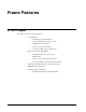
MFC-8320-N LEDs
The front edge of the MFC-8320-N, and the CFM-8320 in the frame door, have LED indicators for
cooling module fan, alarm, and communication activity.
The CFM-8320 provides LED and Alarm switching controls to the front edge of the 8320 frame door.
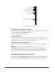
LED displays and descriptions are provided in the following table: