
User manual

8321 User Manual •
••
• (V 1.1) Page 27
the screw. If necessary, remove any cards from the frame that would interfere with
easy access and lines of sight.
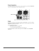
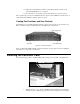
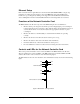
2. Insert the MFC-8320 frame controller card, with the component side out as shown in
Figure 11, into the card guides along the dividing wall between slot 20 and the PS-
8300 section of the frame, ensuring the card does not touch the Card Retaining
Screw.
3. Slide the card in the slot until firmly seated and so the Card Retaining Screw hole on
the bottom front edge aligns with the mounted nut beside the bottom guide slot.
4. Tighten the Card Retaining Screw through the mounted nut and the MFC-8320 Card
Retaining Screw hole, to ensure the card does not move from the slot.
5. Close the door, power up the frame, and check the operation of the fans. If the fans
do not operate, verify that the MFC-8320 is seated properly in the frame backplane
and is aligned to the Fan PCB when the door is closed.
This completes the installation of the MFC-8320 controller card for the CFM-8320 Cooling Fan
Module. Next you will learn the general functions and controls available on the MFC-8320 controller
card.
Functions of the Controller Card
The MFC-8320 controller card component of the CFM-8320 performs several functions:
• Monitors frame power usage and sets the fan speed accordingly (higher power consumption
requires higher fan speed for adequate cooling). The fans always run at maximum speed for 5
seconds after the fan door is closed, then adjust to the appropriate level based on power
consumption.
• Monitors the frame door and PS-8300(s) to ensure that fans in all units are operating
correctly.
• Monitors the fan door and notifies the user if it is left open too long.
• Monitors the status of other cards in the frame via the internal bus.
• Generates alarms if any of the monitored functions develop errors.
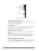
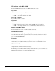
Controls and LEDs for the Controller Card
This section provides information on the jumpers, buttons and LEDs for the MFC-8320 controller card.
The location of the LEDs and controls for fan, alarm, and communication activity are shown in the
following figures.