
User manual

Page 26 8321 User Manual •
••
• (V 1.1)
11. Tighten the 8 nuts until they just make contact with the rubber grommets on the
8321A-016 Fan PCB. Do not over tighten.
12. Reconnect the door to the frame extender arms with the two screws from step 4.
This completes the procedure to install the Fan Board component of the CFM-8321 module. Next you
will learn about the CFM-8321 functions and user controls.
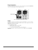
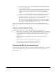
Cooling Fan Functions and User Controls
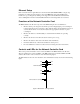
The CFM-8321 provides LED and Alarm switching controls to the front edge of the 8321 frame door.
Refer to Table 4 for details on LED functions for the MFC-8320 controller card.
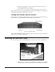
Figure 10. Frame Door Features
Next you will install an MFC-8320-N controller card. Refer to the appropriate section for installation
instructions for your specific controller card.
Installing the Controller Card
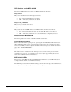
Use the following procedure to install the MFC-8320 controller card component of the CFM-8320:
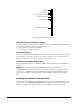
Figure 11. MFC-8320 Fan Controller Card and Unscrewed Retaining Screw
1. With the frame door open, unscrew the MFC-8320 Card Retaining Screw (Part No.
850-040) enough to eliminate any protrusion into the card guide slot on the right of