
User manual

8321 User Manual •
••
• (V 1.1) Page 25
Cooling Features
The standard 8321 frame can be also be ordered as the 8321-C version, with the Cooling Fan Module
installed as original equipment from the factory. However, for customers wishing to increase the
ventilation on their standard 8321 frames, the optional CFM-8321 Cooling Fan Module is available as
a field upgrade kit.
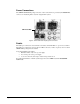
The CFM-8321 module consists of a fan board, which installs in the frame door, and a controller card,
which installs in a designated frame slot. The controller may be either an MFC-8320, which provides
fan control and local alarm monitoring, or an MFC-8320-N , which provides fan control, alarm
monitoring, and support for remote monitoring and control via Ethernet. Installation instructions are
provided in this chapter for both types of controller cards.
Installing the Cooling Fan Module
This section includes instructions on installing the Fan Board component of the CFM-8321 module and
an outline of the Functions and User Controls of the module. After you install the CFM-8321 module,
you must install the MFC-8321 or the MFC-8321-N controller card.
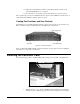
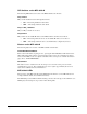
Fan Board Installation Instructions
Use the following figure and procedure to install the Fan Board component of the CFM-8321:
1. Open the CFM-8321 package and remove the components. Verify that all necessary
components are included.
• Fan PCB 8321A-016
• Fan Filter S985-006
• 8 nuts 650-007
• 8 washers 960-025
• MFC-8321(-N) Frame Controller Card
2. Turn frame power off.
3. Open the frame door.
4. Carefully remove the door from the frame by unscrewing the two screws that attach
the door to the extender arms.
5. Place the frame door inside up on a clean antistatic workspace.
6. Insert the Fan Filter with the panhandle over the smaller fan vents and the cut corner
adjacent to the LED pipes already on the door. Gently push the filter down so the
mounting bolts pass through cleanly.
7. Place a washer on each of the 8 mounting bolts.
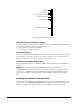
8. Align the Fan PCB with the fans up so the LED pipes pass through their board holes.
9. Ensure the Alarm Mute button clears its door hole and that the Fault and Fan Fail
LEDs clear their door holes while you slowly press the Fan PCB down onto the 8
mounting bolts. See Figure 11 for details on these item locations.
10. On the frame door, check that the Alarm Mute button pushes in and out without
binding.