
User manual

Page 16 8321 User Manual •
••
• (V 1.1)
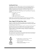
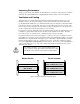
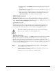
Cable Connections
SMPTE Alarm BNC
Power Supply Inputs
Ethernet Connector
RossBUS Connector
Reference Connectors
Figure 2. Frame Cable Connectors
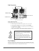
Power Cable Connection
Use the following procedure to connect the power cable:
1. Connect the supplied power cable’s three prong male connector to an AC outlet.
2. Connect the cable’s female IEC connector to the frame socket marked PSU 1.
3. If the Redundant Power Supply option is installed, repeat step 1 and 2, plugging the
second IEC connector into PSU 2.
4. Each AC connector includes a Powerlock, which is designed to retain the power cable
connector. Clip the Powerlock over the shoulder of the inserted AC cable end.
5.
Warning
Warning
Hazardous
Voltages
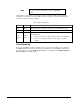
Note — In some countries, it may be necessary to supply the
correct mains supply cord. Use only an approved IEC 320
C-13 type A/C line cord rated for a minimum 10A at 250V and
certified for the country of use.
Further, the safe operation of this product requires that a
protective earth connection be provided. This protective earth
is provided by the grounding conductor in the equipment’s
supply cord. To reduce the risk of electrical shock to operator
and service personnel, this ground conductor must be connected
to an earthed ground.
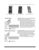
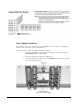
Rear I/O Modules
Depending on the frame model you purchased, there may be variations in the BNC rear I/O modules
connected to it. If the frame was ordered with cards requiring custom rear I/O modules, the appropriate
modules will be installed at the factory or included with the card modules.