® 7660 AX/EX 7665 AX/EX Rim Clamp® Tire Changer For servicing single piece automotive and most light truck tire/wheel assemblies Safety Operating Installation Maintenance Instructions Instructions Instructions Instructions READ these instructions before placing unit in service. KEEP these and other materials delivered with the unit in a binder near the machine for ease of reference by supervisors and operators. 1601 J. P.
Table of Contents Operator Protective Equipment Definitions of Hazard Levels ................................1 Owner’s Responsibility ........................................1 Principal Operating Parts .....................................2 Operating Instructions .........................................3 Bead Loosening and Demounting ....................3 Mounting ...........................................................6 Inflation ..................................................................
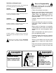
Definitions of Hazard Levels Identify the hazard levels used in this manual with the following definitions and signal words: DANGER Watch for this symbol: DANGER Owner’s Responsibility To maintain machine and user safety, the responsibility of the owner is to read and follow these instructions: • Follow all installation instructions. It Means: Immediate hazards which will result in severe personal injury or death.
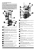
Principal Operating Parts 19 Know Your Unit Compare this illustration with the unit before placing it into service. Maximum performance and safety will be obtained only when all persons using the unit are fully trained in its parts and operation. Each user should learn the function and location of all controls. Prevent accidents and injuries by ensuring the unit is properly installed, operated, and maintained.
OPERATING INSTRUCTIONS The unit must be properly operated and properly maintained to help avoid accidents that could damage the unit and injure the operator or bystanders. This section of the Operating Instructions manual review basic operations and use of controls. These instructions should be reviewed with all employees before they are allowed to work with the machine. Keep these instructions near the machine for easy reference.
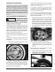
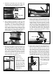
5. Determine the mounting side of the wheel. The mounting side is the narrow side of the drop center. (Tire removed in Figure 4 for clarity.) Narrow Side Drop Center Long Side Figure 7 - Adjust Swing Arm to Position Head Roller Figure 4 – Determining Mounting Side of Wheel 6. Place tire/wheel assembly on table top with mounting side up (Figure 5). Use the clamp control pedal to move the clamps inward (push pedal down) or outward (toggle pedal up).
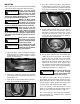
H. The vertical tool clearance may change with machine use and should be inspected often. Failure to maintain the proper clearance may result in damage to the wheel rim and/or tire. 14. Lift and hold the tire at an angle so that the lower bead is resting in the drop center directly across from the demount head, and is loose below the demount head (Figure 12). Insert the smooth curved end of the bead lifting tool down over the forward end of the mount/demount tool and below the lower bead.
MOUNTING This information must be read and followed carefully to prevent accidents and injuries during mounting. Check tire and wheel carefully before mounting. Make sure the tire bead diameter and wheel diameter match exactly. Consult the Rubber Manufacturer's Association for approved rim widths for tire sizes. WARNING 4. Place tire over wheel and move swing arm into position making sure the value stem is at the 6 o’clock position.
INFLATION Use the bead seal pedal for bead sealing only. Do not use this control to bead seat or inflate the tire. Inflating the tire with this feature bypasses the pressure liminting features and could lead to over inflation and possible tire explosion. Do not use this pedal without a tire and wheel positioned on the table top. Dirt and debris could be blown into the air with enough force to injure the operator or bystanders.
T. If tire and wheel are properly lubricated and operator cannot achieve bead seal after 3 or 4 attempts, the valve core may be removed from the valve stem to allow more air flow into the tire to assist with bead seal. After bead seal is achieved, remove the chuck and reinstall the valve core. Bead Seating Operator should always stand behind Inflation Guard and keep hands, arms, and entire body away from the tire during the remaining bead seat and inflation procedures.
AA: Wheels with an asymmetrical hump have a larger “ledge” type hump around the wheel except at the valve hole making them more difficult to mount and demount (Figure 21). Always loosen the beads near the valve stem on both sides of rim.
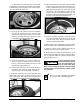
Aluminum and Custom Wheels Follow instructions provided for standard steel wheels, except: AC. After loosening and lubricating both beads, rotate the table top until the clamps are in the 12, 3, 6, and 9 o'clock positions (Figure 24). AD. Clamp wheel from the outside. Position rim edge into clamp at 12 o'clock position. Lower the wheel and depress the clamp control pedal. Slowly move the clamps inward until they securely contact the outside edge of the rim.
10. Hold lifting tool in place, depress the table top rotation pedal momentarily to jog the wheel a short distance. Check the wheel and tire to verify that operation is not causing damage. The lifting tool can usually be removed after jogging the wheel a short distance. Continue to jog the wheel to allow the tire sidewall to flex as it crosses the rim edge. Continue short rotations until top bead is completely demounted (Figure 30). Performance Tires and Wheels - Mounting 1.
CUSTOM AND SPECIAL WHEELS TUBE TYPE TIRES If a custom wheel is damaged in mounting or dismounting, STOP, and avoid damaging the other wheels. Continue only when the cause is identified and corrected. Mounting 1. Avoid pinching or forcing the tube. CAUTION Alloy Wheels Some manufacturers offer wheels with little or no drop center. These are not DOT approved. The tire or wheel - or both - can be damaged and the tire could explode under pressure, resulting in serious injury or death.
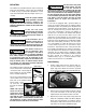
STAGES OF INFLATION Review these descriptions and diagrams carefully. Refer to them as necessary during bead sealing, bead seating, and inflation to verify that you are proceeding properly and safely. Requires rubber lubricant on both upper and lower beads. Bead Sealing A 140 PSI air blast from the table jets creates an air curtain to aid in bead sealing. Never exceed 10 PSI in the tire during bead sealing. The tire will contain about 2 PSI when bead seal is obtained.
MAINTENANCE INSTRUCTIONS Read and follow all the maintenance instructions provided in this manual to keep the machine in good operating condition. Refer to the other materials received with the unit and to the service bulletins from the manufacturer for additional instructions on proper maintenance and service. Regular inspections and proper maintenance are essential to preventing accidents and injuries.
Separator/Lubricator Maintenance Check oil and water levels regularly, and perform these maintenance items weekly: Check operation of the pressure limiter as shown and described below at least monthly: A. Disconnect air supply to machine. 2. Connect the inflation hose to an empty service tank with a pressure gauge (gauge should read 0). Use a tank with a 250 PSI pressure rating. B. Drain water from the separator by unscrewing the petcock on the bottom of bowl.
Robotic Arm Maintenance A. Grease the robotic arm to maintain smooth rotation. Grease fittings have been provided at the pivot joints. B. Check bolt torque periodically at pivot joints. Proper Torque is 200 ft. lbs. Maintain Bolt Torque at 200 Ft. lbs. The unit is furnished with a 1/4" pipe thread male fitting for easy connection. This connection is located on the right side of the rear of the machine. A 1/4" ID hose (or pipe) for connection to the machine is satisfactory.
77050/7055/7060/7065 X/EX Rim Clamp Tire Changer • 17
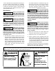
ONE WORD FOR SAFETY R.I.M. READ INSPECT MOUNT READ… INSPECT… MOUNT… Mounting and inflating the wrong size tire can get you hurt. Read the size on the tire and make sure it matches the rim. Be especially careful about putting a smaller tire on a larger rim, such as a 16-inch tire on a 16.5-inch rim. Before you put any tire on a rim, inspect the rim for rust, tough spots, bent edges, or cracks that could prevent the tire from seating right.