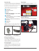
6450 2D/3D Heavy Duty Wheel Balancers See ÌBalancing Your First Tire on page 1. Safety Operating Maintenance Installation Instructions Instructions Instructions Instructions READ these instructions before placing unit in service. KEEP these and other materials delivered with the unit in a binder near the machine for ease of reference by supervisors and operators. 1601 J. P. Hennessy Drive, LaVergne, TN USA 37086-3565 615/641-7533 800/688/6359 www.ammcoats.com HENNESSY INDUSTRIES INC.
IMPORTANT SAFETY INSTRUCTIONS READ ALL INSTRUCTIONS 1. Eye and face protection recommendations: “Protective eye and face equipment is required to be used where there is a reasonable probability of injury that can be prevented by the use of such equipment.” O.S.H.A. 1910.133(a) Protective goggles, safety glasses, or a face shield must be provided by the owner and worn by the operator of the equipment. Care should be taken to see that all eye and face safety precautions are followed by the operator.
Owner’s Responsibility To maintain machine and user safety, the responsibility of the owner is to read and follow these instructions: • Follow all installation instructions. • Make sure installation conforms to all applicable Local, State, and Federal Codes, Rules, and Regulations; such as State and Federal OSHA Regulations and Electrical Codes.
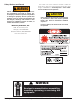
Safety Notices and Decals WARNING Failure to follow danger, warning, and caution instructions may lead to serious personal injury or death to operator or bystander or damage to property. Do not operate this machine until you read and understand all the dangers, warnings and cautions in this manual. For additional copies of either, or further information, contact: Hennessy Industries, Inc.
Standard Safety Devices • STOP key for stopping the wheel under emergency conditions. • A hood guard of high impact plastic that is designed to prevent the counterweights from flying out in any direction except towards the floor. • A hood switch interlock system that prevents the machine from starting if the guard is not lowered and stops the wheel whenever the guard is raised. Important: Always read and follow the information box instructions.
Table of Contents Important Safety Instructions ................................ ii Mounting Wheel on Spindle Shaft ................14 - 15 Owner’s Responsibility .............................................iii Standard Back Cone Mounting ............................... 14 Operator Protective Equipment ................................iii Standard Front Cone Mounting ............................... 15 Definitions of Hazard Levels .....................................iii Alternate Mounting ...........
ÌBalancing Your First Tire 1. Turn the machine OFF then 8. Inboard center bar blinks. ON (resets machine). Note: If an inboard corrective weight is |Note: The machine wakes up using standard clipon wheel weight locations (Clip 1 & Clip 2) and wheel dimensions. not required, the wheel will stop at the outboard corrective weight location, go to step 11. 9. Attach inboard corrective weight. 2.
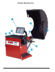
Principle Operating Parts ❶ ❺ ❷ ❹ ❸ ❼ ❻ ❽ ❿ 2 • Important: ❾ Always read and follow the information box instructions.
Know Your Unit Compare this illustration with the unit before placing it into service. Maximum performance and safety will be obtained only when all persons using the unit are fully trained in its parts and operation. Each user should learn the function and location, of all controls. Power Switch The ON/OFF decal (figure 4) indicates the ON/OFF switch location at the back of the balancer. Prevent accidents and injuries by ensuring the unit is properly installed, operated and maintained.
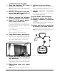
When prompted by balancer instructions, use the offset arm (figure 6A) to enter A & D measurements automatically. Pull the arm out and up against the wheel flange; hold it still at the clip-on weight location (figure 6B), against the wheel flange, and wait for the BEEP. Offset Arm In Home Position Note: The T2 - Tape Direct Select™ Weight position is the only mode that requires the A2 & D2 dimension measurements.
Using The Line Laser If the T2 - Tape (hidden Tape-A-Weight®) location is selected, use the line laser to align the offset arm with the laser locator dot (figures 8 & 7B); entering A2 & D2 measurements automatically. Grasp arm at the line laser and pull out and up to the wheel flange (figure 6B). Hold arm still at the clip-on weight location and wait for BEEP. Then, before returning arm to home position, press button on line laser to activate the line laser beam.
Laser Guided Operation™ System The operator must select T2 - Tape Laser Locator to activate the Laser Guided Operation™ feature, see page 8 for the button selection. This Direct Select™ weight location is used when placing hidden adhesive weights at the inner area of the wheel and is the required weight location selection for the Behind Spoke mode.
Setting Wheel Dimensions (DIM) Before a wheel can be balanced, wheel dimensions must be entered into the computer. Definition of Dimensions (DIM) A = Offset The distance measured from the balancer (“0” on offset arm) to inner plane of the rim (inner weight location). W = Width The width of the wheel at the rim flanges, measured with the calipers as shown in figure 13. Note: Only use calipers provided by the wheel balancer manufacturer because others may not be the same.
Control Panel Function and Review Control Panel Quick Reference If you select/press … Then … a Direct Select Weight key (Clip on the Wheel Cross-section diagram, the activated weight location illumi1, T1-Tape, Patch Static, T2-Tape, nates. T3-Tape, or Clip 2) the T2-Tape key Laser Guided Operation™ mode activates. the Dynamic/Static key(s) additional balance modes may be accessed. For additional information, see Balance Options, page 11.
❻ ❶ ❷ ❸ ❹ ❼ ❷ ❽ ❺ ❾ Figure 14 - 6450 3D Control Panel Reference Important: Always read and follow the information box instructions.
Weight Display and Weight Position Windows Two weight display windows, one inboard and one outboard, are positioned above the wheel cross section diagram. After a wheel measurement cycle, the balancer calculates the corrective weight amount and indicates it in the appropriate display window. All weight readings are shown in ounces or grams. The “Total Static” window indicates the value of the total static unbalance. See MATCH BALANCE (Optimization) on page 16 for further details.
Direct Select™ Weight Placement Location Before spinning the wheel, use direct select to indicate weight placement locations as follows: Note: When the machine is turned ON, the balancer defaults to truck mode and 2-plane dynamic mode using standard clip-on wheel weight locations (Clip 1 and Clip 2) and wheel dimensions. Clip 1 Top Center - select this location to place a standard clip weight on the inboard rim flange.
Balancing Using Direct Select™ A variety of wheel configurations can be balanced using this wheel balancer. Read through this section, it will help in determining which mode and options are best suited for certain wheel assemblies. Refer to pages 1 - 7 to balance the wheel, for measurement and weight placement techniques. Refer to pages 8 - 11 for Control Panel functions.
4. Rotate the wheel toward front so the laser locator dot is behind the first spoke; press SPOKE 1 (indicator illuminates). 5. Rotate the wheel toward rear so the laser locator dot is behind the second spoke; press SPOKE 2 (indicator illuminates). Now at the spoke 2 location, the outboard center bar stops blinking and the two bars on either side blink. Note: The laser locator dot will stop blinking.
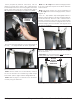
Mounting Wheel on Spindle Shaft CAUTION Avoid back injury, seek assistance when lifting heavy tire/rim assemblies onto the balancer shaft. CAUTION Hubnut must engage threads for at least four full turns. Failure to tighten hubnut securely or to force wheel firmly against the faceplate may result in serious personal injury. Select the most appropriate mounting method for the wheel you are balancing.
Standard Front Cone Mounting Can be used with all cones (do not use spring). This method works well with most truck wheels where the bolt circle is less than 275 mm. 1. Select a cone that best fits into wheel center hole. 2. Lift wheel onto threaded shaft. 3. Slide selected cone onto shaft with the small end against the wheel. 4. By lifting wheel from bottom, center on cone. 5. Thread hubnut on and tighten with hubnut wrench. If hubnut won’t tighten all the way down, remove cone and wheel.
Match Balance (Optimization) The Match Balance (Tire/Rim Weight Optimization) procedure is used to determine the best mating of tire and rim that will result in the least amount of total unbalance of the assembly. It requires two spins and two rotations of the tire on the rim. Match Balance may be needed when: • The customer complains of ride problems.
Calibration Machine Calibration Important: Use the correct calibration weight amount: a 4-ounce calibration weight in ounce mode. Important: The factory default is set for a 4-ounce calibration weight amount for both ounce and gram weight measurement modes. Therefore only a 4-ounce calibration weight is necessary, regardless of weight measurement mode setting. 6. Lower the hood and press START. Important: It is critical that the inner weight be placed accurately to achieve proper calibration.
12. With the arm still at the edge of the faceplate, enter the A dimension shown on the arm rod. Press the NEXT key. Maintenance Instructions The balancer requires only minor maintenance to keep the unit operating properly. 1. Keep the display clean and clear. Use a damp cloth. Do not use cleaners or solvents which leave oily or filmy residues behind. 2. Keep the adapters, cones, faceplate, threaded shaft, pressure cup, and hub nut clean.
Diagnostic Procedures After Balance Vibration Problems If vibration is still present after balancing the wheels and driving the vehicle on smooth pavement, remove the wheels and recheck the balance. If a wheel is out of balance the cause maybe: • Wheel was not mounted/centered correctly on the balancer. • A weight has come off the wheel (possibly the wrong clip style). Remove the other weights from the wheel and rebalance. • Foreign material inside the tire.
Installation Instructions Setup Receiving The shipment should be thoroughly inspected as soon as it is received. The signed bill of lading is acknowledgement, for the carrier, of receipt in good condition of the shipment covered by our invoice. If any of the goods called for on this bill of lading are shorted or damaged, do not accept them until the carrier makes a notation of the shorted or damaged goods on the freight bill. Do this for your own protection.
Specifications Features Wheel Diameter Range 19.5 - 30 inches • Automatic Data Entry for Offset and Diameter Manual Entry Backup on all Parameters Wheel Width Range 6 - 20 inches • Static-on-Screen™ Maximum Outside Tire Diameter Up to 52 inches • Four Fixed Function Keys, Seven Program Keys for user Friendly Operation • Direct Select™ Weight Placement Location Maximum Tire/Wheel Weight 500 pounds (227 Kg) Dynamic (Standard): Clip-on Weights Mounting Shaft Diameter 2.
85606875 02 12/2011 © Copyright 2010 Hennessy Industries and COATS® All Rights Reserved.